Ideas For Future Posts

Future Post Ideas

It looks like I will be cutting back on the time I spend on writing blogs posts for a while, so I thought I would outline some of the ideas I have for future posts. Just so you know I am thinking of you.

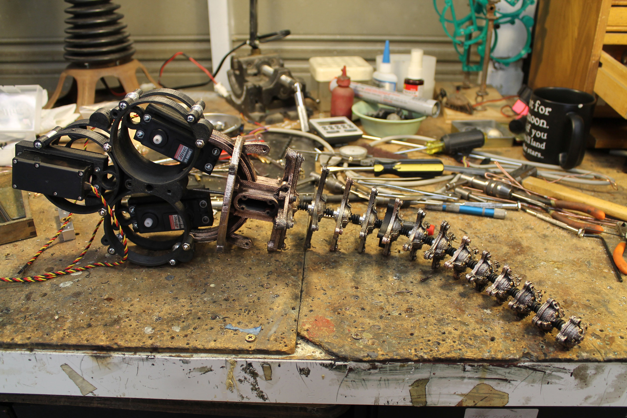
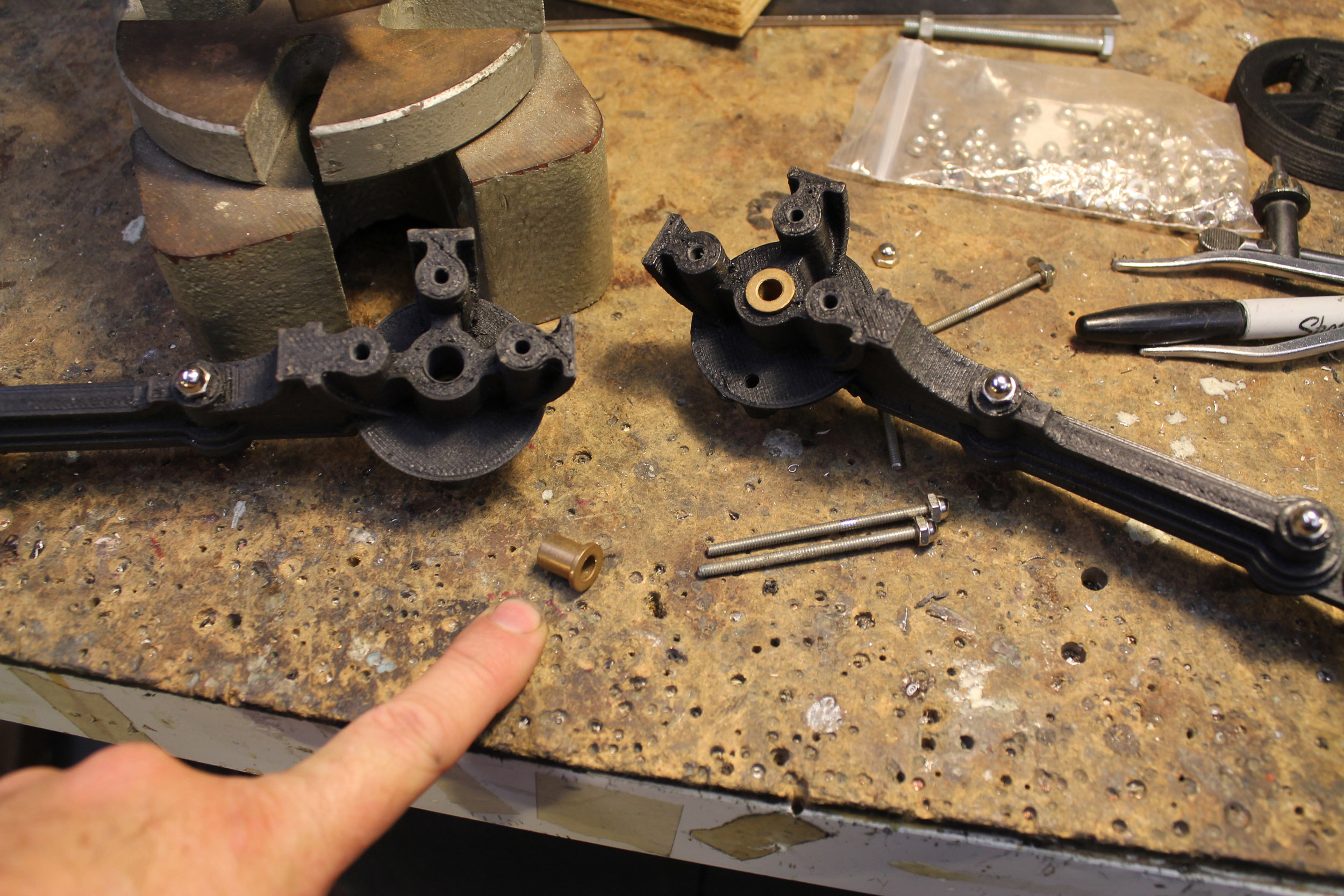
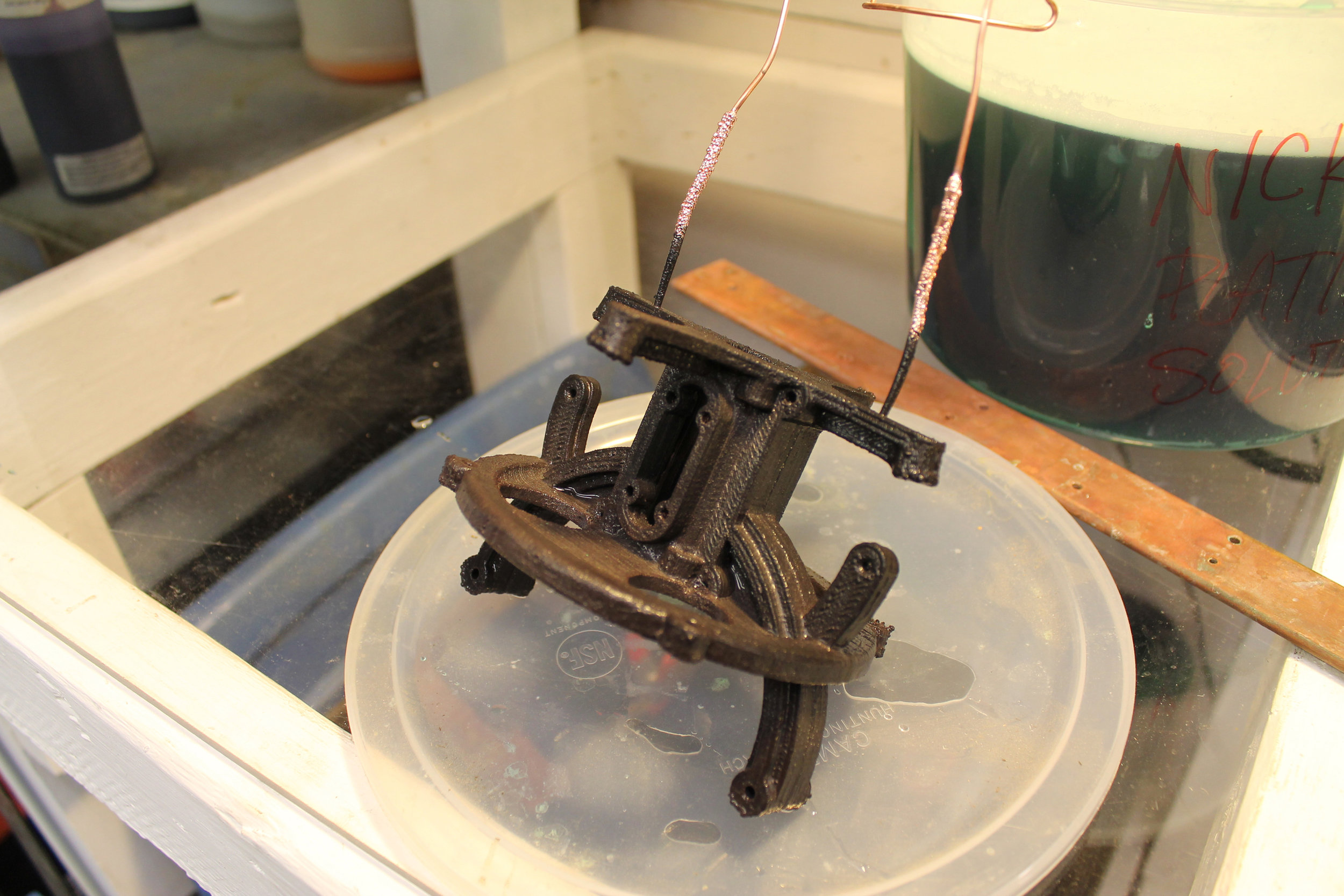
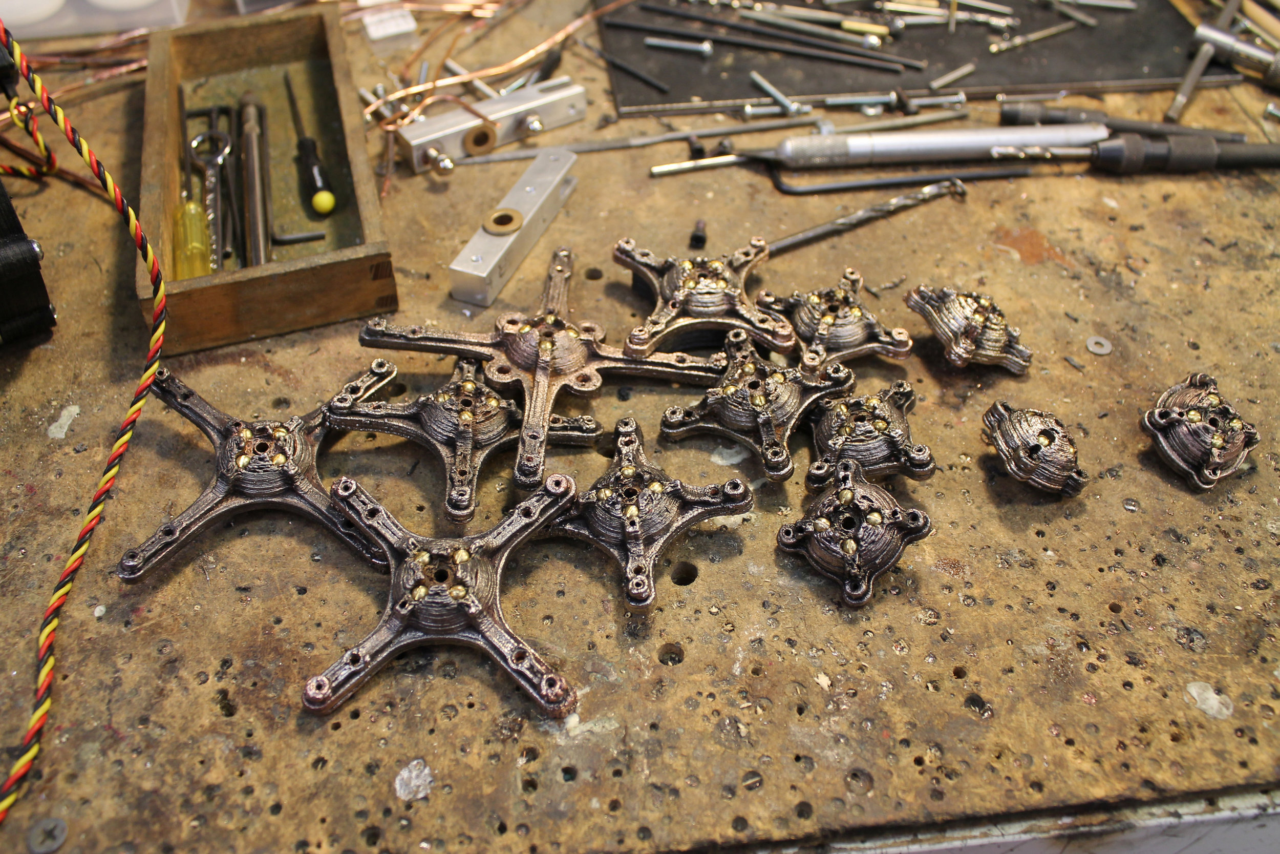
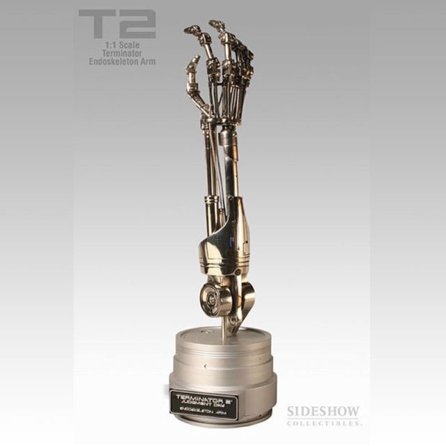
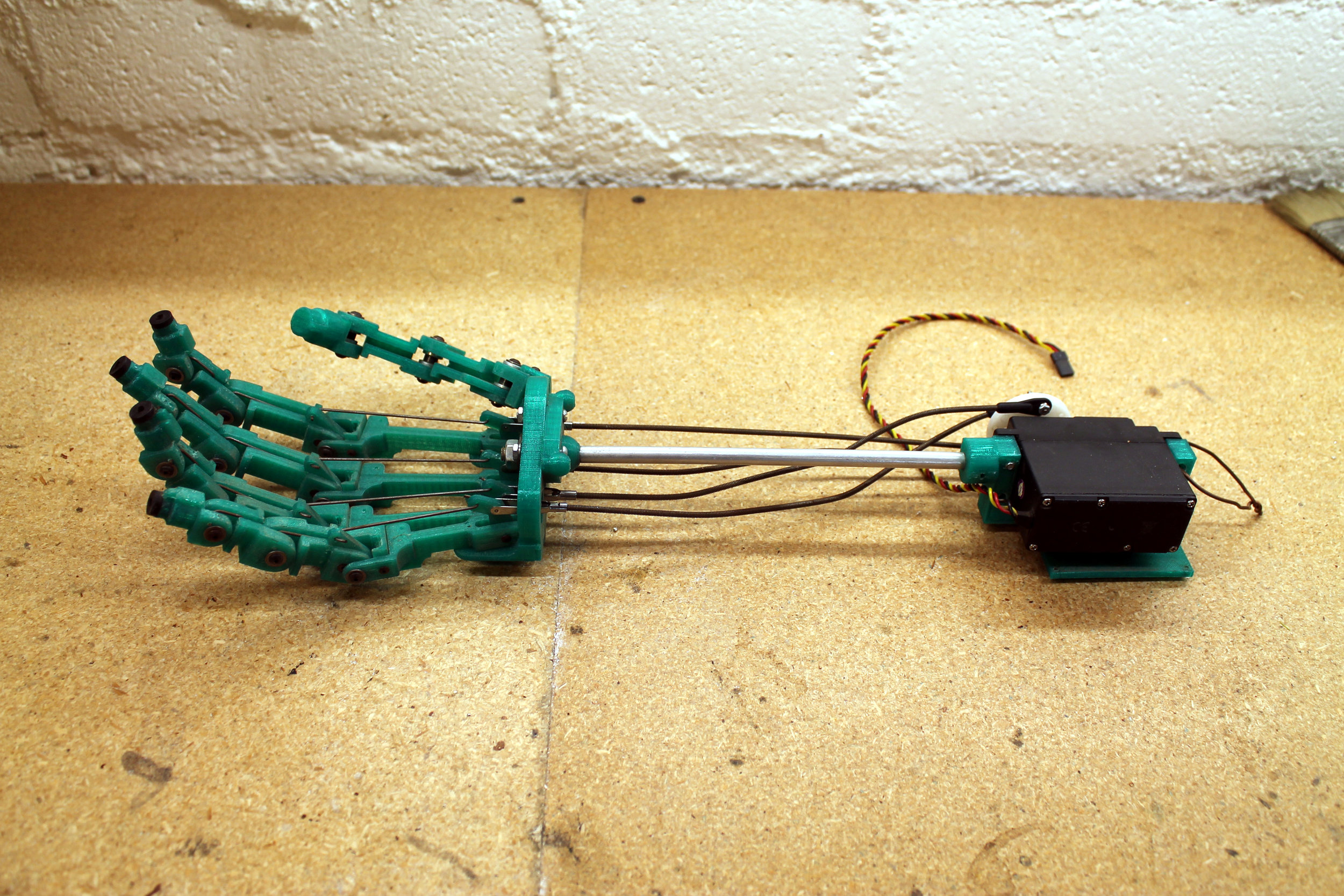
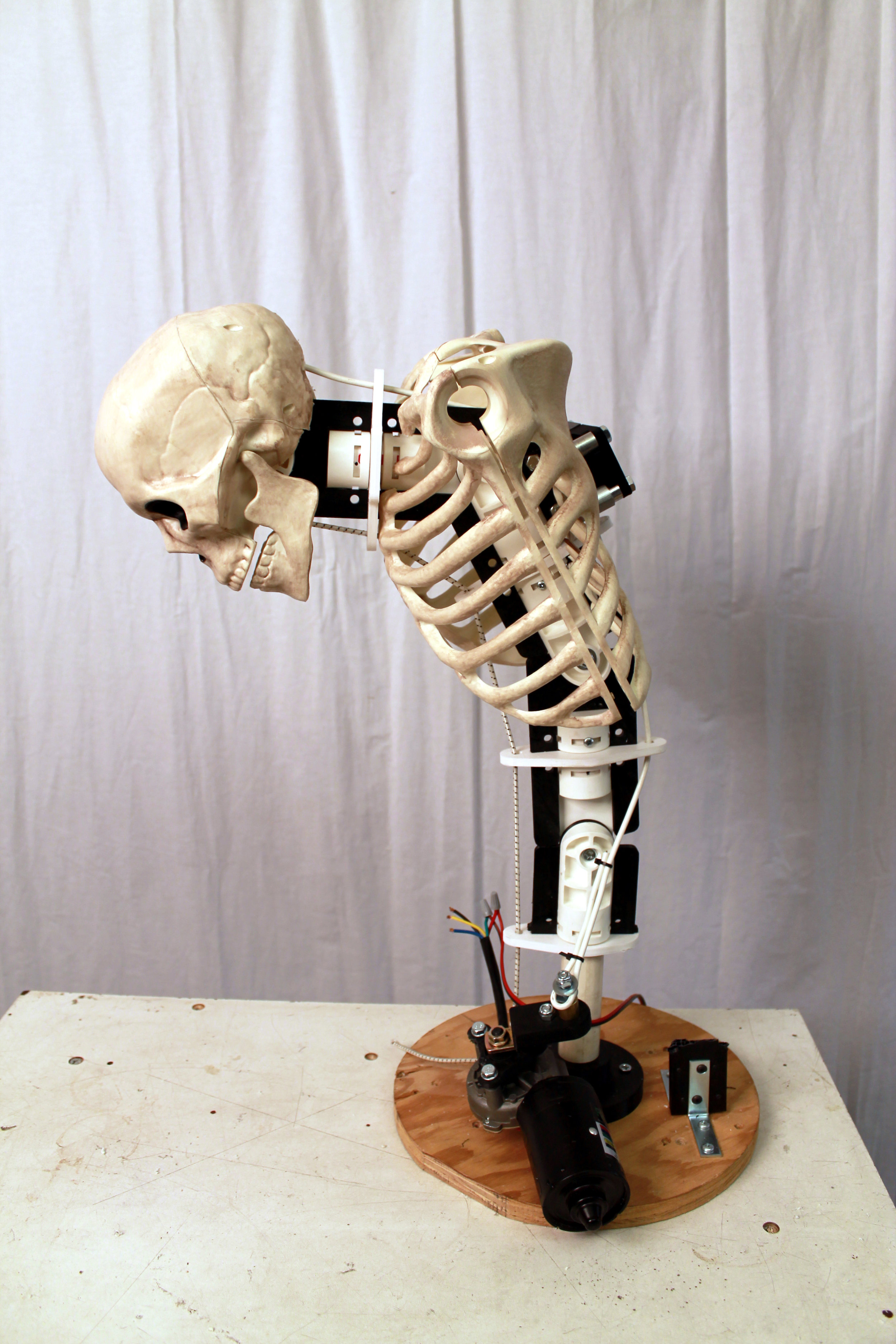
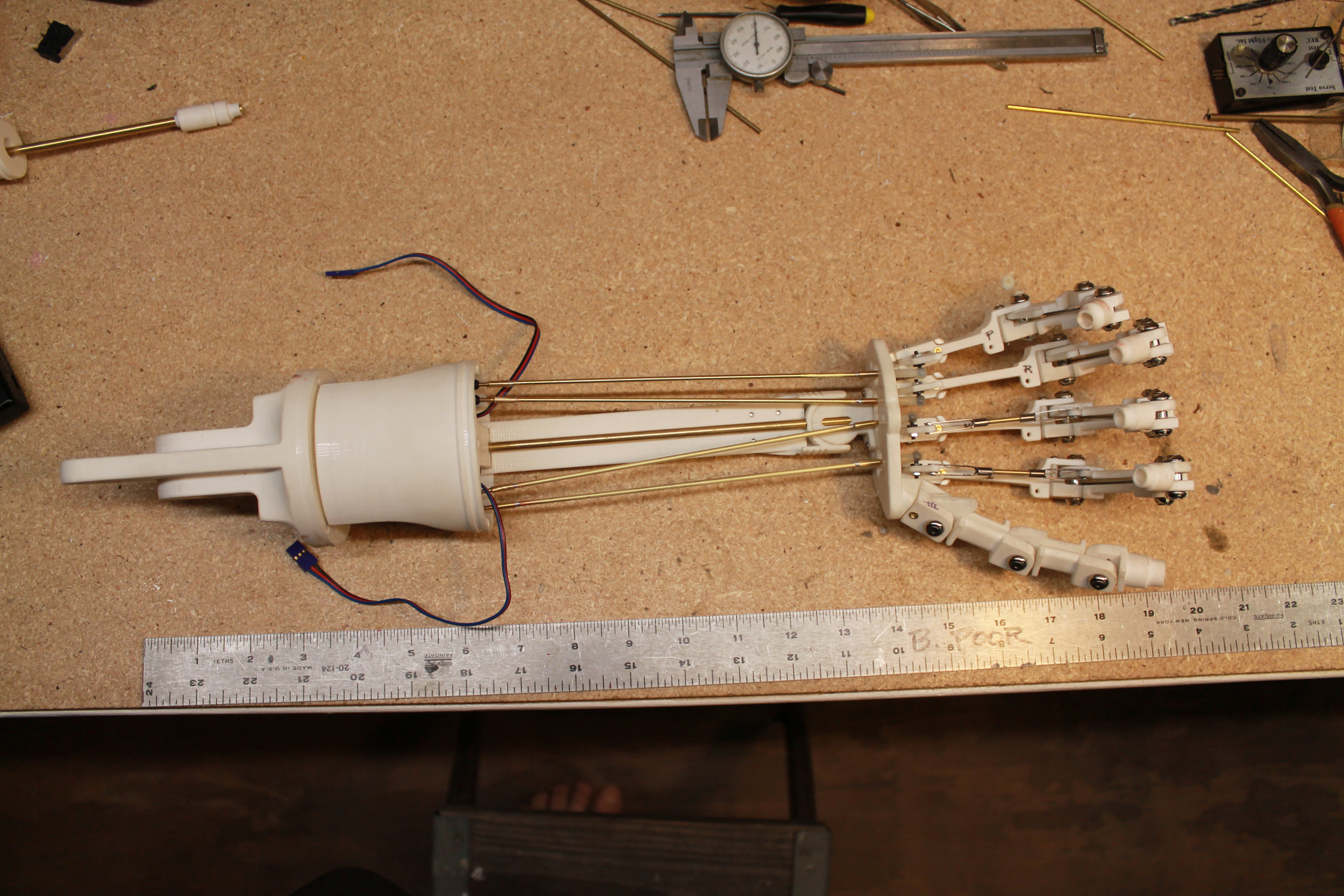
Self-Propelled 3d Printed Terminator Hand

This is a mash up of my 3d printed Crawling Terminator Hand, from six or eight posts ago, and the Endoarm posted to Grab Cad by Simo83. Simo83 saved me a huge amount of work by creating a beautiful model of the classic Terminator Arm and posting it online. Yay for Simo83.


https://grabcad.com/library/endoarm-stl-1


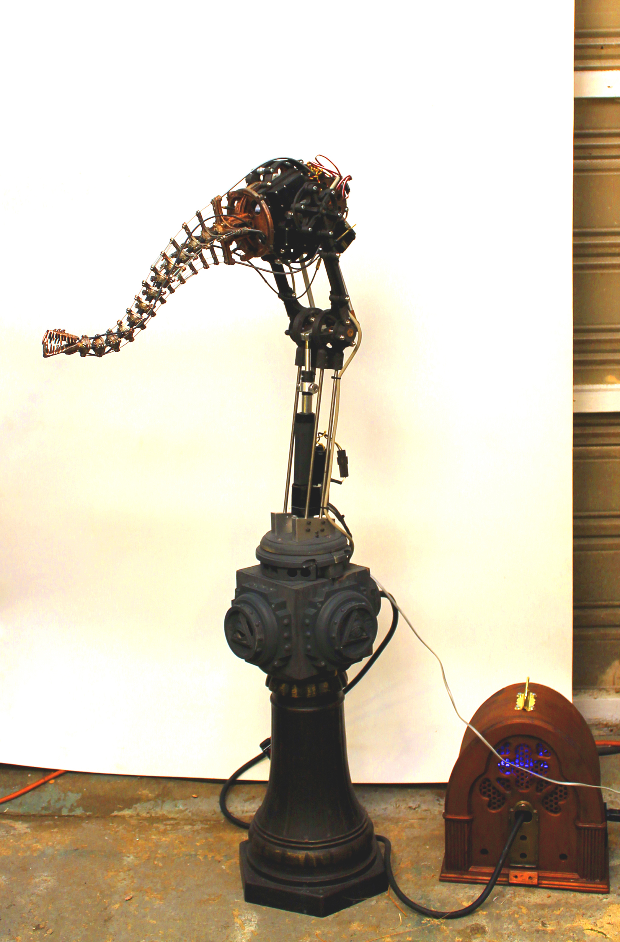
I modified the Endoarm design by making the fingers mechanically functional and then 3d printed the whole thing up in order to create a replica of the T-800 Terminator arm capable of dragging itself along by its fingertips.

TerminatorArm.JPG
TermBuild.jpg

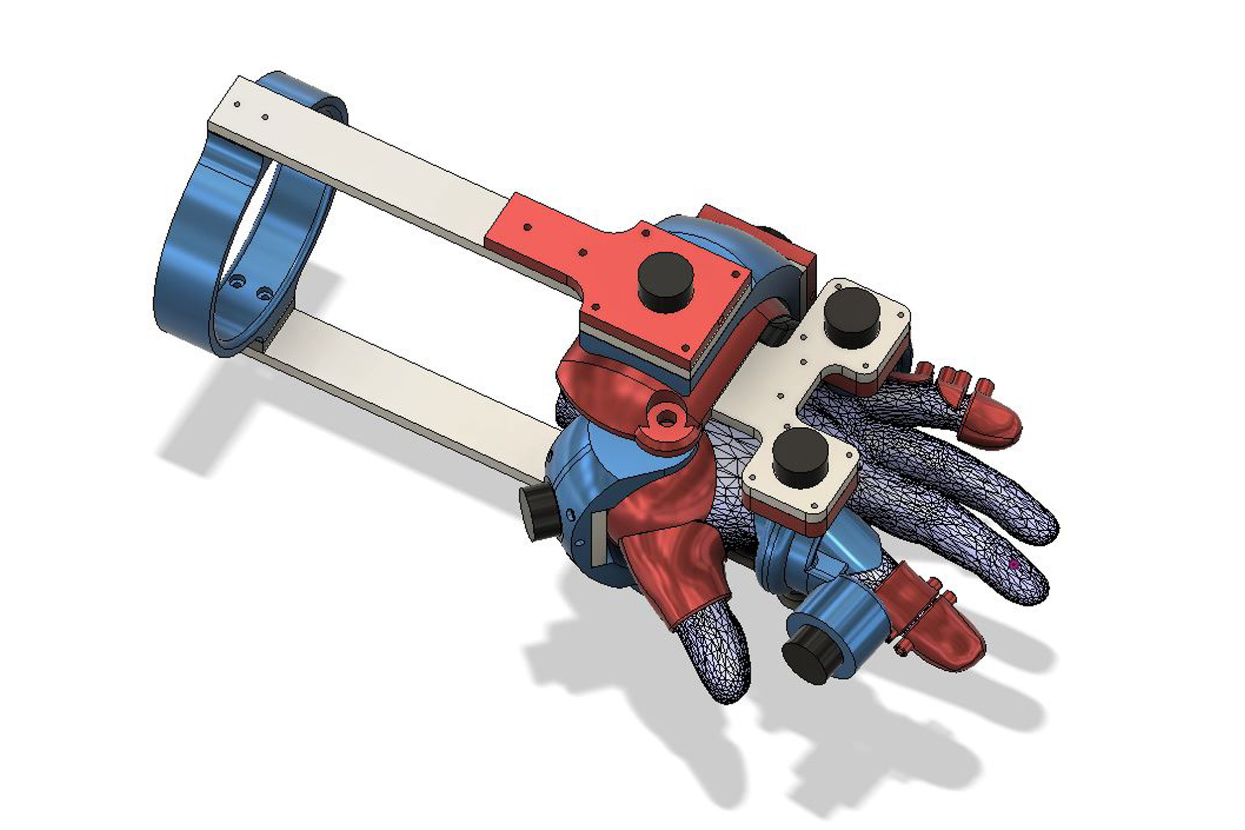
3d Scanning and Working With Scanned Data

I got myself a 3d scanner awhile back and put it through its paces to see what it could do. It could do quite a bit until it stopped working just as its warranty had expired. That’s what I get for being an early adopter but I learned a lot. I will demonstrate the process I went through to create a 3d model of my hand and how I was able to use that data to create a custom fit, 3d printed Telemetry Glove.

HandScan.jpg
TelemetryGlove.JPG

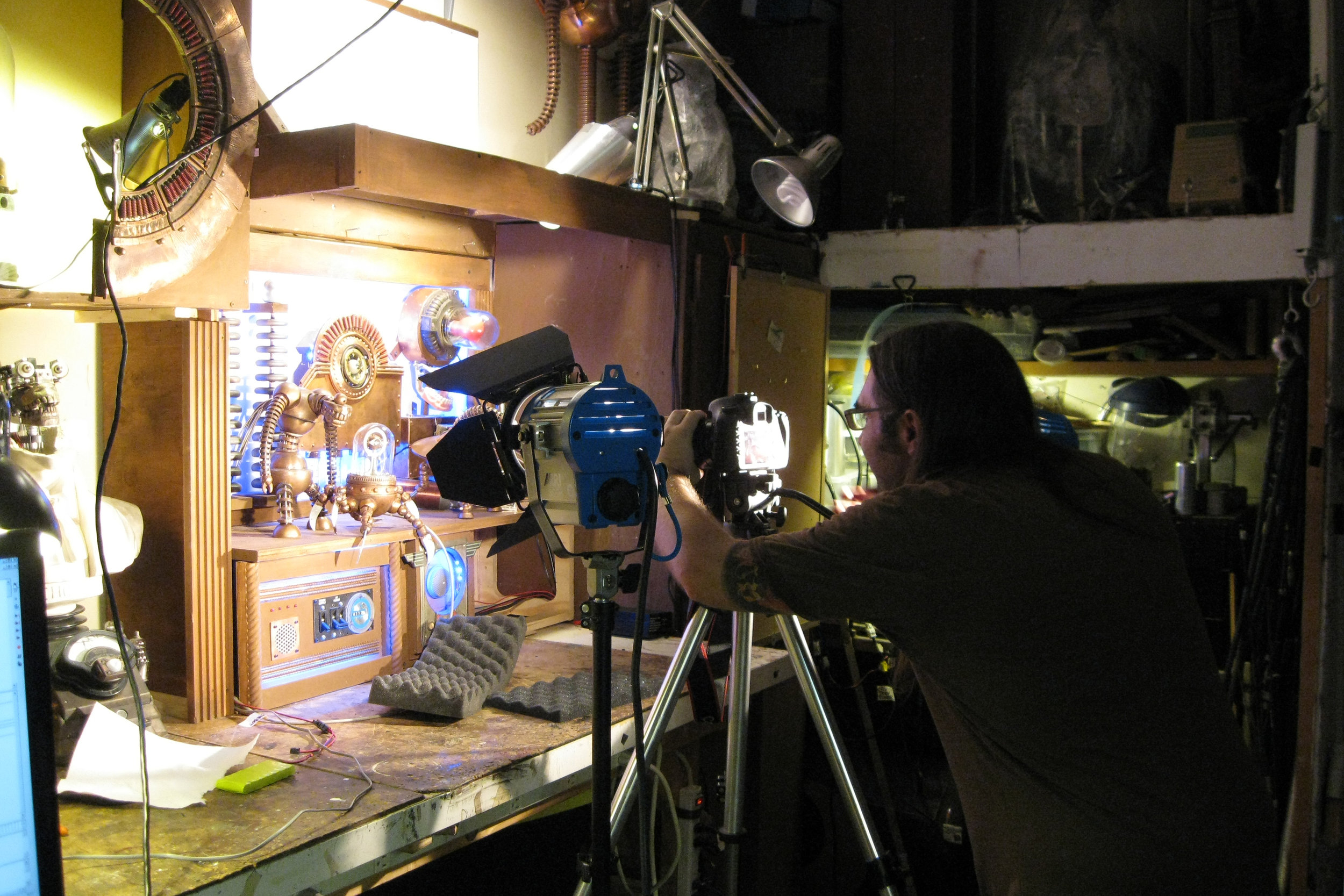
How To Film Animatronic Puppets  


The use of practical creature effects for film and television has become so “old-school” that there is a whole new generation of filmmakers who don’t know how to best utilize it. I am going to create a  primer on some of the basic techniques involved in the process of filming the performances animatronic puppets.


A few years back a videographer friend of mine and I made a short film featuring animatronic puppets called The Escape. A wide range of techniques came into play during filming and I am going to deconstruct the whole process and explain how all the various shots were made to work.

MakeTheEscape.jpg

Stay tuned!

The Brave new Pink Flamingo (Part 2)

BNPF Assembly

Now that the parts are electroplated, it is time to put everything together.

BNF48 NeckMech PlatedAssembled.jpg

The Neck

The neck is the heart of the Brave New Pink Flamingo. It is a 2-stage tentacle mechanism with a 1/8th inch diameter speedometer cable as its core.

BNF50 Servo Installation.jpg

The Body

When I started seriously considering the use of 3d printing for animatronics, my first thought was “how awesome would it be to just print up a mechanism and all I needed to do was drop the servos in?”. Well, it never really worked out that way, but I made a good attempt at that goal with this system. The body was 3d printed as three different layers, and when screwed together, accomodated three servos with pulleys and cable housing terminations, and integrated perfectly with the neck mechanism.


Ther servos I chose for this project were three Hitech 805bb servos. They are fairly strong and really cheap (~ $40 each). There are servos out there that are two thirds the size and are three times as strong, but they cost four times as much. So there you go.

The Legs

Flamingos have long legs and the Brave New Pink Flamingo is no different. This part of the project actually ended up being a tremendous lesson for me in the structural limitations of 3d printed parts.

BNF51 LegStructure Fail.jpg

Aw Snap! I designed and printed the components meant to serve as the legs and hips of the BNPF. After assembling these parts I didn’t like what I saw. So I gave it the “I wonder how easily I can break it” test. Oops, too easily. Back to the drawing board.

BNF55 LegStructure Redesign.jpg

One of the great things about 3d printing is the ability it grants to try out different iterations of and idea without a lot of man hours involved. In the picture above you can see where the first leg structure failed and how I beefed it up in the second. If I had spent the time machining these parts and had this kind of failure, there would have been much wailing and gnashing of teeth. As it was, it was more a matter of “huh, look at that…”. It was a good learning experience.

Designing for the Material

When one learns to design mechanical systems made out of metal, like I did, there are certain things one takes for granted, like strength and durability. So, moving forward with this project, I had to make it a point to stop and think about what I was asking the materials to do. It’s not a difficult thing to do, but it was an interesting process, at the time.

BNF54 LegStructure Redesign.jpg

Here is an example of the shift that took place in my design approach. The project called for the whole body and neck assembly to elevate 120 degrees on a .25” diameter steel shaft suspended between the hips of the BNPF. The idea was to use a .5” bore metal shaft collar to clamp down on a printed plastic hub in order to hold that steel shaft. On the left, is the first hip hub part and the off-the-shelf shaft collar I intended to clamp down over the part. On the right is the redesigned hip hub with a much beefier seat for a much bigger shaft collar. The new shaft collar was something I had to custom make.

Turning custom shaft collars for the BNPF hip hub on my little vintage Craftsman lathe.

Turning custom shaft collars for the BNPF hip hub on my little vintage Craftsman lathe.

BNF57 LegStructure Bushings.jpg

In my new found paranoia about breaking plastic components, I was very concerned about my plan to press fit bronze bushings into my 3d printed parts. I am pleased to announce that, yes, you can press fit bronze bushings into 3d printed parts.

BNF53 LegStructure PressFitNuts.jpg

Here is a good work around for the fact that 3d printed parts cannot be threaded: press fitted nuts in hexagonal recesses. Works great!

Here are the finished leg assemblies.

Here are the finished leg assemblies.

Body Elevation Mechanics

Raising and lowering the body of the BNPF was accomplished with a linear actuator from C.K. Design Technology Inc.


http://www.ckdesigntech.com/wseriesfb.html


It was during the construction of this part of the BNPF that my 3d printer started giving me problems. I had gotten most of the plastic parts I needed so I didn’t it slow me down and continued on using more traditional/old-school machining techniques. In terms of the levers, cranks, and clamps needed for this part of the project, there wasn’t much 3d printing was going to do for me, anyway.

BNF59 BodyElevateMech.jpg
BNF60 BodyElevateMech.jpg
BNF61 BodyElevateMech.jpg

Head Mechanics

The head is a relatively simple yet critical aspect of the BNPF. It is actually made from a model of the jaws of a dragon fish. How cool is that?

scaly-dragonfish-rawscan.jpg
BNF84 HeadDetail.jpg

The neck had to be completely installed and cabled before the head could be dealt with. There is a lot that goes into a 2-stage neck mech, especially if there is going to be a cable actuated head mounted on the end of it.

BNF79 NeckDetail.jpg

The Base

To facilitate bringing all the various elements together, the BNPF needed to be mounted on its base. I wanted this critter to stand stand fairly high in relation to the eye line of its viewers, so I chose to mount it upon a metal pedestal that was once part of a decorative lamp post. It is to be displayed in a group art show and these things need to be considered.


In addition to supporting the BNPF and displaying it to its best advantage, the base houses all the various electronics needed to bring this project to life (power, microcontroller, sensors, motor control) . So, it not only needs to be sturdy and look good, it’s interior needs to be accessible while the electronics are installed. The enclosure for the electronics actually required a surprising amount of work.

BNF71 BaseAssembly.jpg
BNF73 BaseElectronics Enclosure.jpg
BNF74 BaseElectronics Enclosure.jpg
BNF83 BaseDetail.jpg
BNF75 AllCommingTogether.jpg

Power Supply and Enclosure

The electronics for the BNPF required two different power supplies and they needed some sort of decorative enclosure. I modified an old radio I picked up at a flea market to serve that purpose.

BNF66 PowerUnit.jpg
BNF67 PowerUnit.jpg
BNF70 PowerUnit.jpg
BNF85 PowerUnit.jpg

The Control Electronics

As an art piece the BNPF looked really cool. However, it was meant to be an interactive, robotic art piece, and as such, it was less than ideal. The problem was that I was using a Basic Stamp 2 as a microcontroller and its capabilities were just too limited. At the time, it was the microcontroller I knew best. The inherent limitations of the Basic Stamp 2, as well as the fact that I had run up against the deadline for the art show, meant that its performance was less than satisfactory. Ah well.


The system I had put together to control the performance of the BNPF consisted of the Basic Stamp 2, a motion sensor, and an array of three sonar range finders. The idea was that the motion sensor would alert the Basic Stamp 2 of the presence of people, the array of sonar sensors would located the location of the nearest target within range, and then the BNPF would respond with some behavior appropriate to the direction and proximity of the nearest target. I have some success in the past with this exact system with animatronic tentacle creatures, but alas, the BNPF was just a bit too complex for it to work well. It needed to be able to respond to its environment with the same level of interactivity as a pet parrot on a perch, which it really didn’t.


I was discussing this situation with Jon McPhalen, who is a big proponent of the Parallax Propellor microcontroller and he has me convinced that the Propellor is the way to go with this kind of interactive, robotic sculpture. Microcontrollers like the Basic Stamp and the Arduino are capable of doing only one thing at a time:  check the sensors, move a servo position, move another servo position, check the sensors again, ect… not really what was needed. The Propellor has parallel processing, which basically means it has 8 individual processors working simultaneously. That means sensors could continuously be scanning the surroundings of the BNPF, servos could be going through complex little behavioral subroutines, and multiple emotional states could be qued up and ready to go once the sensory inputs indicated it was appropriate. Sound great right?


I know people who seemingly eat new computer languages for breakfast. I am not one of them. I have sat down a number of times with a chunk of time set aside for learning to program the Parallax Propellor in the Spin language, and every time it was a miserable experience. I found the learning curve for Spin to be brutal. The Brave New Pink Flamingo stands lobotomized in a corner of my studio to this day. So sad.

Test Circuitry with Basic Stamp 2

Test Circuitry with Basic Stamp 2

BraveNewPinkFlamingo.jpg

The Brave New Pink Flamingo (Part 1)


After that loonnng series of posts I just finished (Wonderful World of Tentacle parts 1 through 5) I thought it would be nice to keep this one short and sweet. This project I am about to describe features a tentacle mechanism, but I cover new information such as the the use 3d printed mechanical parts and how to strengthen printed parts with electroplating.

BraveNewPinkFlamingo Cropped.jpg

The Brave New Pink Flamingo was originally created to be part of the Conjoined 5 group art show curated by Chet Zarr at the Copro Gallery in Santa Monica. It was inspired by the tacky pink plastic flamingos people sometimes use to decorate their yards. “Wouldn't it be so much cooler if they were robotic,” I thought to myself, and so was born the Brave New Pink Flamingo.

BNPF Concept Art

BNPF Concept Art

Retro-Futuristic BNPF

Retro-Futuristic BNPF

BNPF Mechanics

BNPF Mechanics

The Concept

The original concept started off as a retro-futuristic-rocket-ship-looking robot flamingo featuring 3d printed pink parts. However, it evolved into something scarier, probably because I was binge listening to the H.P. Lovecraft Literary Podcast while I was building it. So it goes.


At the time, I was still getting to know my 3d printer and what it could do. I decided the Brave New Pink Flamingo (BNPF) was going to feature a servo operated tentacle mechanism. I like tentacle mechs because they are relatively simple yet can be very expressive. This was for an art piece so simple and expressive were desirable features. In addition to the tentacle mech neck, I wanted it to have jaws. A robotic sculpture with a long, sinuous neck and big, toothy jaws trying to bite people: how cool is that?


I had the opportunity to try out a new material: carbon fiber-filled PLA from Proto Pasta. It seemed like a good choice for mechanical components. I also experimented with electroplating as a way to strengthen and stiffen the 3d printed parts. Electroplated plastic works really well for mechanisms as well as art. Not only does it strengthen and stiffen the parts it gives it a beautiful and durable finish. Most of the animatronic art pieces I've done over the years have featured electroplating. I just can’t seem to help myself.


A microcontroller and an array of an electronic sensors were incorporated into the BNPF to give it some robotic interactivity. Animatronics for use in film usually involves an operator/puppeteer but as a stand-alone art piece I wanted this to be a robot, not a puppet. Alas, this was probably the least successful aspect of this project due to my limitations as a programmer. Improving my programming skills in order to bring the Brave New Pink Flamingo to life is still very much on my bucket list.

3d Printing the Parts

BNF03 NeckPartsPrint.jpg

All of the printed parts for this project we're created on Woody, my Type A Series 1 3d printer. One look at the photo will tell you why I named it Woody.  As a material for mechanical components, carbon fiber-filled PLA has some nice characteristics, primarily it's stiffness and it seems to warp less than regular PLA. However, the main drawback is the wear-and-tear the carbon fiber PLA inflicts upon all the metal parts of the printhead. I managed to get most of the way through two rolls of the filament before the little knurled wheel that feeds the filament through the hot end of the 3d printer was worn smooth. That's not a huge deal if one is prepared to replace printer parts on a regular basis for the sake of using carbon fiber-filled PLA, but I was still unfamiliar with the technology and I was up against a deadline. So, the experience of being in the final phase of the project and having all my prints unexpectedly turn into crap pretty much turned  me off to carbon fiber-filled filaments. I ended up resorting to more traditional machining and model-making techniques to finish this project. Specifically, the feet, the head, and the body shell are fabricated by methods other than 3d printing. They turned out pretty cool, but the added aggravation was not appreciated.

Post-Print Cleanup of the Parts

BNF02 PostPrintCleanup.jpg

A common misconception amongst people unfamiliar with 3d printing is that the parts come out of the printer in pristine condition. This is not the case. There is still a considerable need for what machinists call benchwork. In 3d printing there tends to be loose strands of filament, wonky edges where the parts were adhered to the print bed, and all the holes end up being a little bit undersized. These issues all require some trimming, standing, drilling, and filing. The great part about 3d printing mechanical components is how accurate the fabrication process is. The holes may be a little undersized but they all line up perfectly with each other. I love that.

BNF04 NeckPart BenchWork.jpg

Another underappreciated aspect of the 3d printing process is the characteristic texture that everything ends up with. There may be some really high-end machines out there that can make some beautifully smooth and flawless prints, but I don't own one of those. When I first started working in the film industry I was introduced to the concept of “if you can't hide it, feature it”. In the case of 3d printing, this means you should learn to love that funky texture because it is not worth the hassle of getting rid of it.

BNF08 Textures.jpg

Printer Problems

I was probably 90% of the way through the printing needed for this project when the prints began to fail. I didn’t realize it at the time, but the carbon-fiber-filled PLA really wears upon any metal components of the print head it comes in contact with. The benefits of using carbon fiber-filled filament are just outweighed by this fact, in my humble opinion. The filament strands are indeed strengthened by the addition of little chopped up pieces of carbon fiber but the inherent weakness between the layers of the printed part is not mitigated in any way. The junction between these layers are where the parts are weakest, so there is no real benefit gained by using the carbon fiber-filled PLA filament, though I have to admit, I do like the matte black color of the finished parts.

BNF45 PrinterProblems.jpg

The Machined Parts


As useful as 3d printed parts are, there are certain applications that require metal. Specifically, anything in the body of the BNPF that is going to have threads cut into it will be made of aluminum. Printed plastic parts can be tapped but it won't take too much tightening for a screw to just rip those threads out. There are certain applications where one can get away with that, but for the most part, I try to avoid tapping plastic.


For the BNPF project I turned some simple standoffs on a lathe for securing the various components of the body together. I probably could have used off the shelf threaded standoffs but a little lathe work seemed like a nice change of pace. Additionally, I drilled and tapped a bunch of small aluminum gear blanks for mounting the tentacle segments. The gear blank modifications in particular were a little labor-intensive: lots of little holes to drill and tap. For future 3d printed tentacle projects I have figured out different mounting techniques involving the use of heat set threaded inserts that eliminate the need for the gear blanks, but that is for another project.

Turning Aluminum Standoffs

Turning Aluminum Standoffs

Tapping Threads into Standoff

Tapping Threads into Standoff

Drilling Gear Blanks with Sherline Rotary Table 

Drilling Gear Blanks with Sherline Rotary Table 

BNF26 NeckMech Assembly.jpg

In addition to the aluminum standoffs and the modified gear blanks there are other mechanical components machined from metal. These were the parts involved with moving the whole body and needed to be particularly strong. We'll discuss these when we get to the body elevation aspect of the project.

The Pre-Assembly Process

BNF09 NeckMech PreAssembly.jpg

A pile of parts is pretty uninspiring. So I find it helpful and informative to assemble the components as they are produced, even though I know full well I'm going to have to take everything apart again. The fact is, the more complicated the mechanism, the more assembly and disassembly will take place. One of the guys who taught me how to do animatronics, way-back-when, told me that a project isn't done until you’ve taken it apart and put it back together at least 8 times. And 20+ years later I pretty much have to agree. It's best to keep it to a minimum, for the sake of one's own sanity, not to mention that of your employer, but a certain amount of it is unavoidable. But it's pretty damn cool to see your stuff coming together during that initial pre-assembly.

BNF12.5 BodyAssembly.jpg
BNF13 BodyAssembly.jpg

Servos were used to drive the neck of the BNPF. The servos I chose were three HiTec hs-805BB servos because they are strong, durable, inexpensive, and have nylon gears instead of metal gears. Nylon gears are not as strong as metal gears but they have better wear characteristics and will last longer if not put under too much load. The design of the 3d printed body framework is laid out so as to provide a place to mount the neck, hold the servos in place in relation to the neck, and to provide a structural pivot point for the elevation of the body. This should all become more clear as all the components come together. The elements of the body structure are designed in layers to facilitate the 3d printing process. The the aluminum standoffs connect these different layers together.

BNF15 BodyAssembly.jpg
BNF16 BodyAssembly.jpg

Once I am satisfied with how the various body and neck elements go together I then have to take it all apart for the electroplating process. Yay.

Electroplating Preparation


I have seen examples online of people electroplating 3d printed plastic parts but never for the purpose of making them more structural: only to make the parts prettier. I have utilized electroplating in the past with cast resin parts to make them both stronger and yes prettier.  There is a huge opportunity or making lightweight 3d printed parts more suitable for use in mechanisms, and now I am going to let you in on the secret.


Primarily, the individual components of the neck and the neck strut will be electroplated. These comprise the most visually dominant elements of the BNPF and would benefit the most from being strengthened and stiffened. Some of the other visual elements will also be plated but the neck and the strut are the most mechanically crucial parts to undergo the process.


Once the components are cleaned up, the first step of the electroplating process is to give them a coat of primer. I use an automotive primer as it is of a better quality than the more generic types of primer available from your local hardware store. After the primer is applied, a fairly heavy gauge (18 to 16 gauge) of copper wire needs to be attached in order to suspend the parts in the electroplating solution. The plastic parts will want to float in the plating solution so the copper wire needs to be strong enough to keep the parts submerged during the plating process. Then, a layer of electrically conductive paint is applied to the part. Electrically conductive paint is available from plating supply companies online.


I have found it helpful to apply the conductive paint with an airbrush for anything but the smallest objects. Airbrushing helps to apply the paint evenly but it can be tricky. The conductive paint needs to be thinned down enough to pass through an airbrush but not so thin that it becomes non-conductive. My approach to this is to thin the paint just enough to be able to spray it with an airbrush and no more than that. The texture of the paint can get a little stippled, adding some roughness to the final finish of the metal plate, but I have learned to live with it. The alternatives to applying the paint with an airbrush is to use a paint brush (very labor intensive and inconsistent) or to dip the parts in conductive paint (requiring a lot of paint).

BNF18 PlatingPrep.jpg
BNF17 PlatingPrep.jpg
BNF19 PlatingPrep.jpg

Electroplating 3d Printed Parts

Plating Station

Plating Station

My electroplating system does really well with copper. Copper is the base metal for any plating operation weather it is for gold jewelry or chromed hot rod parts. I allowed the copper layer to build up on the parts for about 12 hours.This creates a layer that is plenty strong for the purposes of the BNPF.

Part ready to be Electroplated

Part ready to be Electroplated

In it Goes

In it Goes

And Out it Comes

And Out it Comes

I also had a small amount of nickel plating solution that I thought I'd make use of, though the finish has never been quite as bright and shiny as it might have been. Don't know why, but it always comes out a little funky. We're making art here not a hot rod; I have embraced the funk. The nickel plate was allowed to go on for about 30 minutes. It came out of the plating tank looking brown and funky, but with some buffing with a soft wire wheel in a dremel tool it shined up fairly well. However, it still retained some of that funky stuff. In future projects, the funkiness increased to the point where the solution just became useless. Perhaps some chemical element was becoming depleted in the solution. Don’t know. Not worried about it. Moving on.

Nickle Plate Set Up

Nickle Plate Set Up

BNF29 NicklePlate.jpg
Fresh From the Take Looking Brown ?

Fresh From the Take Looking Brown ?

Shined Up a Bit and Looking Much better

Shined Up a Bit and Looking Much better

Bunches of Parts for the Plating Tank

Bunches of Parts for the Plating Tank

Coated with Electroconductive paint

Coated with Electroconductive paint

Arranging Parts for Plating

Arranging Parts for Plating

In They go

In They go

And Out they Come

And Out they Come

Nice!

Nice!

Funky Brown Nickle Plate

Funky Brown Nickle Plate

Put Some Shine on it

Put Some Shine on it

I Dig the Textures

I Dig the Textures

This is Going to be the Sweetest Robot Flamingo Ever!

This is Going to be the Sweetest Robot Flamingo Ever!

My First 3d Printed Project: The Crawling Terminator Hand

CTH06_HandMechDetailTop.jpg

I was always interested in 3d printing for the purpose making functional mechanisms. I still had all my mechanical drawings from that previously mentioned Terminator project and decided to 3d print an articulated robot hand. Not just any robot hand, but something capable of dragging itself along under its own power. I wanted to see what 3d printed mechanisms could do.

The Terminator hand design was based upon the T-800 Endoskeleton Arm that used to be available from Sideshow Collectibles. That model was apparently molded directly from a working terminator arm made at Stan Winston Studios for use in the movies. It had the screw heads and accommodations for finger linkages already laid out and the dimensions were exactly what they needed to be to recreate the functional mechanism.

T-800EndoskeletonArm.JPG

The mechanisms for the T-800 hands were originally fabricated using traditional machining techniques ( of course). This meant there were plenty of places to grip the parts in a vise or a 4 jaw chuck for the machining process. These features translated well to the technology of FDM 3d printing, where it is desirable to have flat surfaces to attach to the print bed.

Finger Parts being Grown on 3d Printer

Finger Parts being Grown on 3d Printer

Finished Parts

Finished Parts

CTH04_TerminatorArmTopView.jpg
CTH05_TerminatorArmBottomView.jpg
CTH07_HandMechDetailSide.jpg
CTH08_HandMechDetailBottomThumb.jpg
CTH09_HandMechDetailsBottomPinky.jpg

If I Had It All To Do Over Again: The Thrashing Torso v.2.0


We live in interesting times.


3d printing is becoming a mature technology and can be very useful and making mechanisms. I once heard 3d printing described as a lifestyle enhancement. Speaking as someone who is tired of expending my valuable hours planted in front of a lathe or milling machine, I heartily agree.


Man hours are expensive. Robot hours not so much. The more work that can be delegated to some form of CNC (computer numerical control) machine, the better.


3d printing has its strengths and it has its weaknesses. The trick is to play up its strengths and avoid the weaknesses. Over the past several years I've been experimenting with 3d printing parts for animatronics mechanisms with mixed results. Sometimes plastic just won't do and metal fabrication comes back into the picture. However, there is a lot plastic can do.


The New and Improved Thrashing Torso:


TT2.1.jpg

Since I built the original thrashing torso, all those years ago, a few things have changed.


3d printing is one of these changes. Another change is the introduction of new off-the-shelf products meant for use in Halloween haunted attractions. I've recently been introduced to the Spider Joint from Spider Hill Prop Works. It is a versatile plastic joint used in conjunction with 1 inch pvc pipe to create body armatures. The new Thrashing Torso also uses a 12-volt motor from Frightprops, another haunted attraction oriented business. Additionally, a plastic halloween skeleton is used. Some modifications are required and this proved to be the most time-intensive part of the build.  


A few other refinements have been incorporated into the design. Bungee cord is used instead of springs and clothesline from the hardware store is used instead of steel cable.


All of these changes make the finished mechanism much easier to make, the parts are easier to acquire, and everything is much lighter.

TT2.2.jpg
SpiderJointTorso.jpg


The Breakdown:


Man Hours Required: ~30 hrs.


I spent about a half a day designing the mechanism in Fusion 360 and I estimate another half a day setting up for the 3d printing and cleaning up the parts as they came out of the printer. Only another day was spent assembling the mechanism. Modifying and mounting the plastic skeleton took the better part of two more days, which includes futzing around with clearances and tensioning the bungee cords.  Considering how much time the first Thrashing Torso took to build, this is great.


Cost: ~$158 (total)


    Plastic Skeleton $40

TT2_PlasticSkeleton.jpg
Plastic Skeleton Label


    Fright Props motor $25

dual-speed-high-torque-prop-motor-with-parking-mot1-p-1_1_1.jpg


    Spider Joints (x8)  $28

Spider Joint.JPG


    Misc. Components and Fasteners ~$40


    ABS Printer Filament Roll $25


Some Thoughts on 3d Printing:


There has been quite a bit of hype about 3d printing over the past few years. 3d printing is incredibly useful but let me come right out and say that it can be a pain in the ass. The technology is getting better and better all the time, but like any fabrication technique, it takes time to master. This is especially true when 3d printing functional mechanisms. In the next post (or three) I am going to discuss 3d printing and its applications to making animatronics, as well as some of the pitfalls you may be able to avoid.