

WWoT (Part 3) Working With Cast Resin Tentacle Parts
/Cast Parts Clean-up
Step 1: Sanding the Discs
Now that we have our cast parts demolded, they need to be cleaned up. The excess urethane needs to be removed from the castings and the rough edges need to be smoothed before the holes can be drilled out.

Cast discs ready for sanding
A piece of 60 grit sandpaper will work for our purposes. Place the sandpaper on a flat surface and sand each of the discs until they're all nice and pretty.

Sandpaper, God's gift to smoothness...
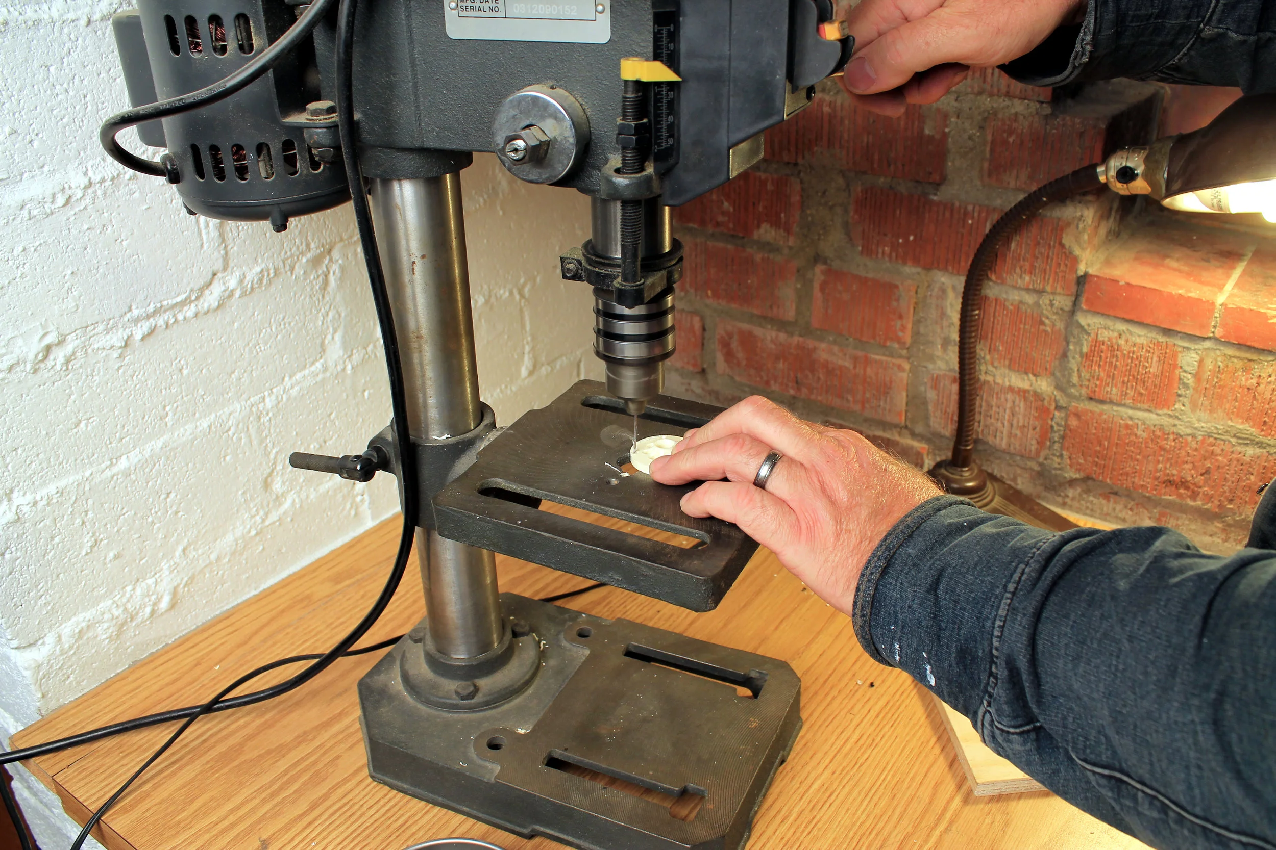
Step 2: Drilling the Discs
Most of the holes (if not all) will need to be drilled out because they will be partially filled after the casting process. The holes need to pierce all the way through the cast urethane discs. I used my cheapy little Harbor Freight drill press for this but a hand drill would probably work as well. I also used a countersink bit to chamfer the holes. You might be able to get away with not doing this step, but I recommend getting rid of all sharp edges on the discs to facilitate unimpeded movement.
Drilling a hole... yay

Chamfering a hole, more yay

Disc Hole Dimensions:
Center Hole: .125” diam.
Outer Cable Clearance Holes: .062” diam.
Inner Clearance Holes: .156” diam
The Tentacle Base
Before getting into the how of drilling out the holes of the tentacle base, I am going to discuss some of the reasons of why they need to be drilled as I describe.
Cables, Housing, and Determining Hole Sizes to Drill:
The base serves the purpose of tying all the elements of the tentacle mech together. The tentacle mechanism is going to be actuated by using cables. This is the same technology used in bicycle brakes and derailleurs: one end of a cable is pulled through a housing, exerting force at the other end. To function properly each end of the cable housing needs to be securely terminated (that is, not allowed to move). We will accomplish this, at the tentacle end, with a press-fit into the tentacle base.
The trick to terminating the housing is to drill a hole of the appropriate depth and diameter to secure the end of the cable housing. The cable housing used in this project are lengths of steel extension spring. The use of steel spring housings is a standard technique in animatronics for film and television, but long lengths of spring housing aren't necessarily easy to come by. There are companies capable of doing custom orders of long lengths of spring housing (upto 25 feet long, typically), but for our purposes I recommend getting the stuff sold online at McMaster Carr. The cable housing commonly used in bicycles tends to be stiff and will inhibit the movement of the tentacle for this particular application. So spring housing is the way to go.
https://www.mcmaster.com/#9664k12/=1dbqbn1
Pulling steel cables through steel housing, during the operation of the tentacle, generates a lot of friction. To help mitigate that, PTFE (Teflon) tubing will be used to line the inside of the housing. Here is a link to some tubing I found on Amazon that looks like it will work.
https://www.amazon.com/gp/product/B076QBDQFN/ref=oh_aui_detailpage_o00_s00?ie=UTF8&psc=1
The dimensions of this PTFE liner is 1.5mm inner diameter and 1.7mm outer diameter (.059” i.d x .070” o.d.). The Amazon source looks a little dicey, as there isn’t much available at the time of this writing. There seems to be plenty of sellers of this tubing on Ebay, but they are all in China, so it will probably take a week or three to get the stuff. The important thing to keep in mind when sourcing this liner tubing is that the outer diameter must be small enough to fit into the spring housing (.081” i.d. in the case of the spring housing from McMaster Carr) and the wall thickness needs to be pretty thin so that it is flexible. Note: I ordered some teflon liner from China via Ebay and I received 3 weeks later. It looks like it will work just dandy. Why I have to order this stuff from the other side of the freaking planet, I just don’t know...
While I am at it, I will give you the info about the cables. The cable used for this project is from Ver Sales and it is the 7x7 non-jacketed, .027” diam variety with the part number #90.
http://www.versales.com/ns/wire_rope/minicable.html
Isn’t all this technical minutia fun? All these details need to be determined so that we know what size holes to drill in the base in order to capture the end of the spring housing securely.

What are the dimensions of the cable housing?
Here is the spring housing with an outer diameter of .125 inches.

Housing with liner protruding
Here is a piece of the Teflon liner protruding from the spring housing. The end of the liner has been split with an X-acto knife so that when the housing is inserted into the hole we are going to drill in the tentacle base, the split ends of the liner will fold back over the spring housing creating a nice, snug fit.

Dimensions with the liner included
The split ends of the liner folded back over the housing add about .005” to the overall width. So in this case I would use a #30 drill bit (.128” diam.) to create the capture hole in the tentacle base. If the housing has a different diameter than .125” then the hole size is adjusted accordingly. Now that I’ve gotten all that explaining out of the way, it is time for a little less talk and little more action.
Step 3: Drilling the Base
If you are using parts cast from urethane resin it will be necessary to drill out the holes of the tentacle base. If you are using a tentacle base that was fabricated on a 3d printer, the holes will be in the correct places but will be a little under-sized, so the following information still applies. However, if you happen to using parts fabricated in a machine shop, your holes are already perfect (presumably) and you may proceed onto the assembly of the 2-stage tentacle. For our purposes, we will assume you are working with cast parts in need of some refinements.

Here is a diagram of the tentacle base showing the layout of the holes. Most of the holes simply pass through the base. It is important that the 4 housing capture holes (marked in red) do not go all the way through, because they need to provide a physical stop for the cable housings. The .062” holes go all the way through so as to allow the cables to pass through.

Once again, I used my little drill press in order to keep the holes straight.

Cast base prior to drilling
This photo shows the tentacle base prior to any holes being drilled. The .25” inch holes around the perimeter managed to be reproduced during the molding and casting process, but all the other holes need to drilled out.

Cable housing clearance holes drilled
Here is the base after I have drilled out the center hole and the four clearance holes around it. The center hole will capture the central, flexy-shaft of the tentacle while the four holes will allow the cable housings for the upper segment of the tentacle to pass through.

The flip side
Here is a photo of the bottom of the tentacle base showing the central hole and the clearance holes.
The next step is to drill the .062” holes all the way through from the top.

After the casting process, all that remains of the .062” diameter holes, through which pass the cables controlling the lower segment of the tentacle, are some little dimples. These dimples will serve as pilot holes. Use a .062” drill bit (or anything reasonably close to that size) and drill all the way through from the little dimples on the top side, through the base. Then flip the base over, so that the cable capture holes can be drilled from the other side.


Using the .130” drill bit, drill down each of the .062” holes to a depth of about .75”. This is the cable housing capture hole. Do not drill all the way through, or it is not a capture hole. It is an entirely different kind of hole.
At this point, I am REALLY bored with describing how to drill holes. And because everything is all about me we are moving on to the assembly phase of the project.