

WWoT (Part 4) Tentacle Mech Assembly
/Tentacle Mechanism Assembly

Materials Required:
Misc. Small Components
Here are the various components needed that can be obtained from www.McMaster.com
(1) .125” bore shaft collar #9414t3
(1 pkg. of 100) .125” bore grommets #9600k11
(1 pkg. of 100) .25” bore grommets #9600k14
(1 pkg. of 50) 6-32 threaded inserts #92397a113 (only one of these is needed, but they come in packages of 50, oh well)
(8, 36” lengths) extension springs .125” o.d. #9664k12
These are the things needed from www.versales.com
Microcable #90.0 (about 40’ is needed, as the project is presented)
(1 pkg. of 100) Copper stop sleeves #871-32-b
Other components (with suggested suppliers)
(40’) PTFE (Teflon) Tubing ~1.5mm i.d., ~1.8mm o.d. (you will have to resort to Ebay on this one, this supplier seems like a good bet: www.ebay.com/str/ATOPELEC?_trksid=p2047675.l2563
Speedometer cable (all that is needed is the steel flex shaft, not all the sleeving and connectors, any auto parts store will have it, for example: www.autozone.com/drivetrain/speedometer-cable/pioneer-speedometer-cable/1672_345317_6211
(1’) Polyurethane tubing .25” i.d., .375” o.d. (available at any hardware store)
Tools:
Here is a quick run down of the tools needed to make a 2-Stage Tentacle Mechanism.

Hand Tools
From top left to bottom right:
Micro torch
Nut driver (7/16th inch)
Crescent wrench
Tap handle
Needle nose pliers
Felco cable cutters www.versales.com
Nicopress crimpers www.versales.com
Ball-end Allen wrenches
Calipers
Tweezers
Xacto knife
Tape measure
Drill Bits
These are the various drill bits, counter sinks, and center drills needed.

Power Tools

The very first power tool I would recommend that anybody should buy would be a cordless drill motor. Don’t leave home without it.

I picked this little bench grinder up from Harbor Freight Tools a couple years back and it has proven itself well worth the 50 bucks I spent on it.

This drill press also came from Harbor Freight. I love Harbor Freight.
Machine Tools:
Metal Parts vs Plastic Parts
Sometimes machined, metal parts are the only way to go. It is usually best to try to minimize the need for machined, metal parts, but occasionally you have to go there. In the case of this tentacle mechanism, I fabricated two parts using a lathe and a milling machine with a small rotary table. It is possible for you get by without them, but in this case, we're going for the best possible results. I'm not above cutting some corners now and again however in my opinion, these two exceptions where unavoidable. One of the greatest advantages of aluminum parts over plastic is that aluminum can be threaded to take a screw: plastic, not so much.
In a tentacle mechanism, it is important that the discs do not rotate on the central flexible core. If the parts do rotate the tentacle will become less controllable. The best way to eliminate the rotation is to make all the discs out of aluminum so that each individual disc can be secured on to the central shaft with a set screw. That is a lot of machining and tapping and set screwing. Satisfactory results can be gotten by set screwing the disc at the very tip of the tentacle and the disc at the transition between the top segment and the bottom segment of the tentacle (known as the termination disc). The central shaft can also be secured in the base of the tentacle with a set screw, but this is optional. Securing these points of the tentacle will ensure its controllability.

The other reason for machining parts is to be able to press-fit the steel cable housing into the termination disc between the two segments. Plastic parts will either not be able to hold the press fit housing or will simply break.
For this project, a lathe is required for turning the disks to the proper thickness and diameter. A milling machine with a rotary table is necessary or drilling the holes in the disc evenly and accurately. It is possible that somebody who is a whiz with a hacksaw and a hand drill could get adequate results but using machine tools will always get the best results.
Lathe
The lathe I used to make tentacle parts is a 70 year old Logan. They started making these right after World War 2 when steel was available for things other than the war effort. It was meant to be the type of lathe one would have around the house for those little metal fabrication chores that commonly pop up (?). Yeah, anyway… They were built to last and there are still plenty of them around, as well as parts, information, and very active website forums full of machinists who dig these old machines. It is a good machine for making animatronic puppets.

Parting is such sweet sorrow...
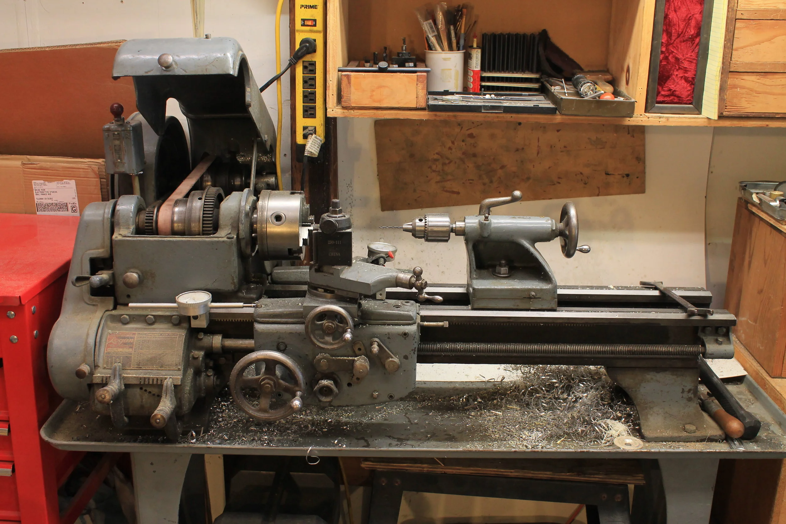
My Logan Lathe
Milling Machine
In my little shop I have what is effecionatelly known as a “Baby” Bridgeport. That is a J head Bridgeport mill with a 32” table, rather than a 40 “ standard table. When Bridgeport milling machines came out (early 60s?) everyone realized what turds mills had all been up to that point, and all manufacturers of milling machines basically started making Bridgeport clones. Awesome machines with only one down side: they weigh 2000 pounds. Try getting one of those into your apartment or dorm room.
However, there are options to the towering mountain of mechanical awesomeness that is the Bridgeport milling machine. From personal experience, I can recommend the Sherline benchtop milling machine. I had one for years and made a lot of cool stuff with it. I used my Sherline rotary table clamped in the vise of my Bridgeport mill to drill the termination disc for the 2-Stage Tentacle Mechanism we are discussing.
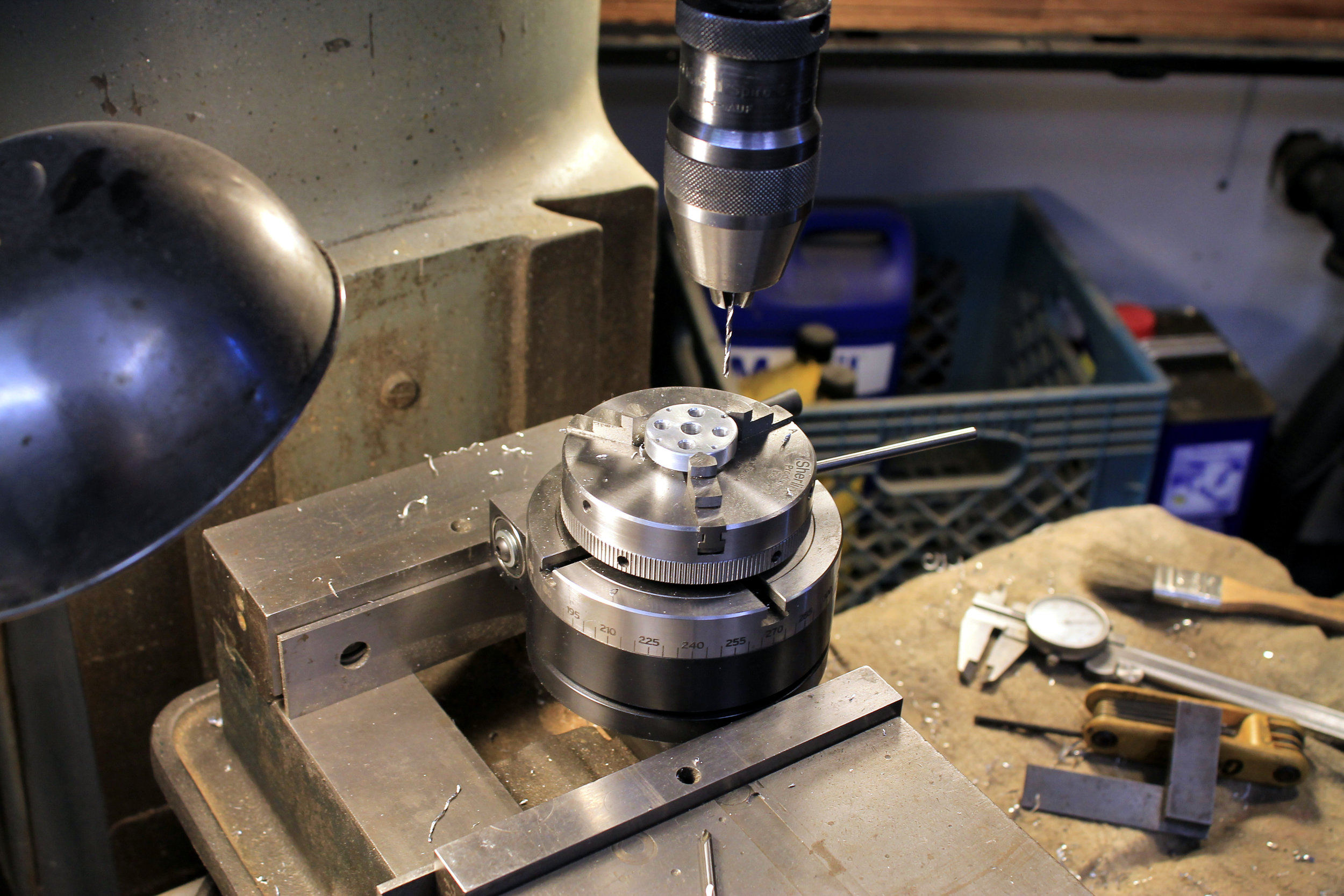
Sherline rotary table is great for small parts
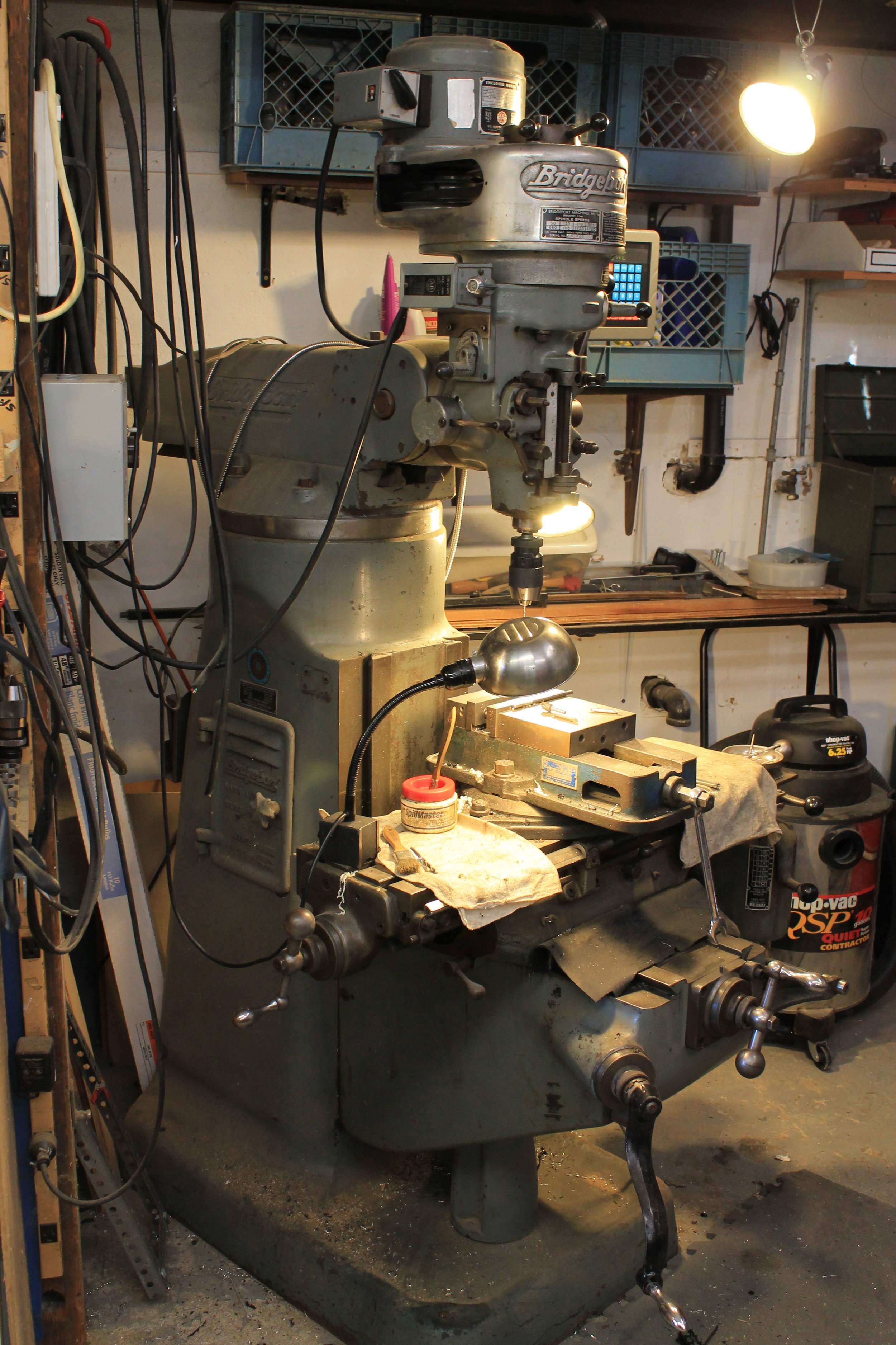
Baby Bridgeport
So, in the spirit of sticking with the Instructables format… Step 1!
Step 1: Machine the Aluminum Tentacle Tip and Termination Disc
Yes, it is possible that these two parts could be produced via casting or 3d printing, but they won’t last long. These parts really should be made of aluminum and that means machine tools. I will not go into the step by step process of how to make these parts with a mill and lathe: presumably, if you are a machinist , you can figure it out.

The unavoidable aluminum parts
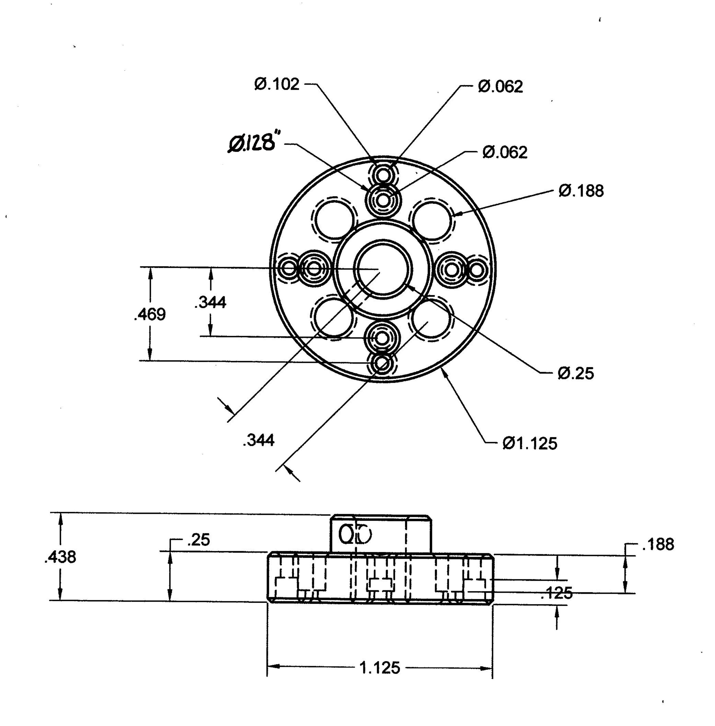
Aluminum Termination Disc Drawing

Tentacle Tip Drawing
Tentacle Pre-Assembly:
Once all the various discs are finished it is time to string all the parts together on the central shaft. We do this initial pre-assembly so as to be able to determine the lengths of the cable and cable housings. Also, it’s kind of exciting to finally see things coming together.
Upper Tentacle Segment
Step 2: Cut Speedometer Cable
The entire tentacle is going to be about 12 inches long. The speedo cable will run the entire length of the tentacle so cut it to be about 15 or 16 inches long. It will extend into the base and be secured there. The excess will be trimmed later. To cut speedo cable I use either cable cutters or a dremel tool with an abrasive cut off wheel.


Step 3: Pre-Assemble Upper Tentacle Segment
Start assembling the upper segment by installing the machined aluminum tip on the speedometer cable with a set screw. Then, begin sliding the discs onto the speedo cable, from smallest to largest, like beads on a string. Each disc is separated from the others with a rubber grommet of appropriate size (.125” i.d.). For the upper segment of the tentacle I am using three of each of the five different sizes of discs to create a tapered form. This will give us a length of approximately 6 inches.


Lower Tentacle Segment
The lower segment tentacle discs are strung on a piece of .25 inch (outer diameter) polyurethane tubing. The steel speedometer cable of the upper segment will be inserted through the polyurethane tubing of the lower segment. The lower segment needs to be stiffer than the upper segment because it supports the weight of the entire tentacle mech and needs a little help. The urethane tube provides the needed, additional stiffness.
Step 4: Pre-Assemble Lower Tentacle Segment
It is time to string the lower segment discs onto the urethane tube, each separated with the appropriately sized grommets (.25” i.d.). The lower segment is going to be about 6 inches long, so cut the polyurethane tubing about 7 inches long. The extra length will be needed for mounting the tentacle into its base. For the lower segment, we are using 10 cast urethane discs and one machined aluminum disc to get a 6 inch length. There are four different sizes of cast discs on the lower segment: three each of the smaller sizes and only one of the largest. Start by mounting the aluminum disc on the tubing and then stack the grommets and cast discs behind it, going from smallest to largest.
I have seen other tentacle mechanisms online where all the discs are of the same diameter. This is obviously done for the sake of simplicity. In nature, tentacles are tapered: fat at the base and pointy at the tip. There are two reasons for this arrangement: the fat base has more mechanical advantage and the skinny tip weighs less and is easier to move. So, while the manufacture of various different sizes of tentacle discs is a lot of work, it does make for a better tentacle.


Step 5: Insert Lower Segment Into Base and Upper Segment Into Lower Segment
Once the components of the lower segment are assembled, insert the end of the tube extending from the bottom of the tentacle into the tentacle base. Then, insert the excess length of speedo cable extending from the bottom of the upper segment into the polyurethane tube of the lower segment. The pre-assembled tentacle allows us to exactly determine the lengths of the cables and housing.


Step 6: Determine the Finished Lengths of the Cable Housing
For the purpose of this demonstration I am keeping the lengths of the housing relatively short. There is going to be only about 18 inches of housing between the base of the tentacle and the cable controllers. The cable housings can be made considerably longer without negatively affecting the performance . 12 to 15 feet are the maximum lengths I would recommend. Cables will stretch a bit during use and the longer the length of cable the more the stretch. Stretched cables will require tightening and tuning to maintain controllablity.

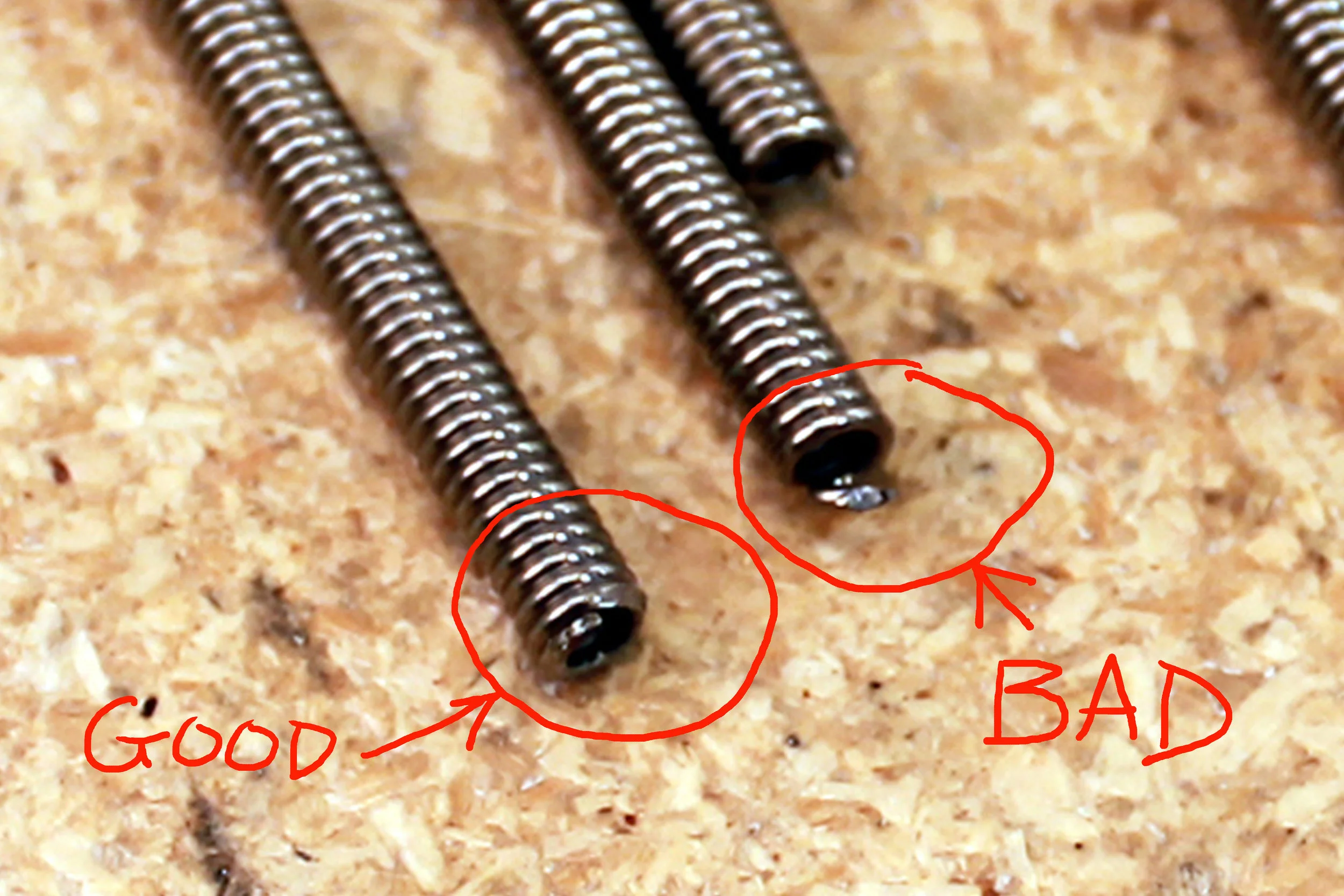
Step 7: Cut and Debur the Cable Housings
This cable housing is made of spring steel which is tough stuff. To cut the spring housing I either use my cable cutters or I use a dremel tool with an abrasive cutting wheel. I then deburr the ends with my trusty little bench top grinder. It is important that there be no little sharp bits on the ends of the housing to impede the movement of the cables or interfere with inserting the housing ends into their capture holes.
There will be two sets of four housings, of different lengths. The longer set will be for the upper tentacle segment and the shorter lengths are for the lower segment. In this case, the housings for the lower segment are 18 inches long, while the housings for the upper segment are 25 inches long. These lengths do not have to be exact. One of the great things about cable actuation is that there is some fudge factor when it comes to lengths. As long as the lengths are relatively close to what is needed (give or take and inch), all is well.


Step 8: Run the Teflon Liner Through the Cable Housings
The next step is to run lengths of Teflon tubing inside of the steel spring housing. When working with short lengths of housing (as in this case) I prefer to cut lengths of Teflon tubing off the roll first a few inches longer than the cable housing. For longer lengths, I will keep the liner on the roll, for the sake of tidiness. Insert the Teflon tubing into the housing, being careful not to create any kinks, and feed the liner all the way through till it protrudes out the other end. Once the liner has been strung completely through the housing, trim the Teflon tubing so that there is approximately 1” of tubing sticking out of either end of the housing. These 1” excess lengths of Teflon tubing will be split with an Xacto knife so that when the cable housing is inserted into a capture hole the split ends of the Teflon tubing will fold back over the exterior of the cable housing and create a nice snug fit. This really is a snazzy technique for terminating cables housing.


Step 9: Modify Discs For Housing Clearance
Both of the upper and lower segments of the tentacle have their own sets of four cables and housing. The cables that go up to the top segment must pass through the lower segment without adversely affecting the movement of the bottom half of the tentacle. To help facilitate the movement of the housings within the lower segment I used a Dremel tool to open up the lower disc clearance holes a bit. When the housings run up through the lower segment of the tentacle they do a little quarter turn helical spiral from one end to the other. By opening up the clearance holes for the housing to pass through, we will relieve some of the tension that would otherwise interfere with the movement of the tentacle. The discs nearest the aluminum termination disc between the two segments will require the most pronounced modification with the Dremel, while those farthest will require none. Dremeling out the top 3 or 4 discs of the lower segment will probably be sufficient.


Lower Tentacle Segment Assembly

Step 10: Press Fit Threaded Inserts Into Urethane Tube
The lower segment of the tentacle gets assembled on a piece of quarter inch polyurethane tube. The aluminum termination disc is to be set screwed on to this tubing. In order to give the set screw something to bite into, we are going to press fit a threaded insert into the end of the tubing. The threaded insert will cause the tubing to expand so we will need taper the end of the tubing with a piece of coarse sandpaper. Otherwise we will not be able to slide the discs over the tubing. Inner diameter of the threaded inserts will need to be opened up with a drill so that the eighth inch barometer cable of the upper segment they freely pass through. I drilled the insert out with a #29 drill bit (.136” diam.) to allow the .125” speedo cable clearance to pass through. I put an inset into both ends of the tube but only the end with the termination disc was necessary. After all these years, I am still making it up as I go.


Step 11: Press-fit Longer Cable Housings Into Aluminum Termination Disc
We are now going to install the cable housings for the upper tentacle segment into the aluminum termination disc. With all the grommets and cast resin discs removed from the polyurethane tubing, secure the aluminum termination disc to the end of the tubing with a set screw. Use the threaded metal insert pressed into the tubing to give the set screw something to bite into.
There are two sets of cable housings, one set longer than the other. The longer set are the cable housings for the upper segment. There should be about 1" of Teflon liner poking out of either end of each housing. These ends need to be split before inserting them into the termination disc. Use an Xacto knife to carefully slice end of the Teflon liner as shown in the photograph. When when press-fit into the termination disc the to split halves of the Teflon liner will fold-back creating a nice snug fit within the capture hole.
The outer diameter of the cable housing we are using is .125". The folded tabs of Teflon liner will add a couple additional thousandths of an inch to that dimension. If the capture holes in the aluminum termination disc were drilled correctly (.128” to .130” diameter) the ends of the spring housing should press snugly into the holes without too much problem.


Step 12: Slide Lower Segment Discs and Grommets onto Urethane Tube
Once the cable housings have been press fitted into the termination disc it is time to install the rest of the discs on to the lower segment of the tentacle. Start with the smallest discs first and work your way down to the largest disc, keeping each disc separated with a rubber grommet. Feed the four cable housings from the termination disc through the access holes drilled in the cast discs. The housings should slide freely through these holes. Otherwise, they will impede the movement of the tentacle. Once all the discs and grommets have been slid onto the polyurethane tubing there should be a 1” length of tubing left uncovered. This end will be secured in the tentacle base.


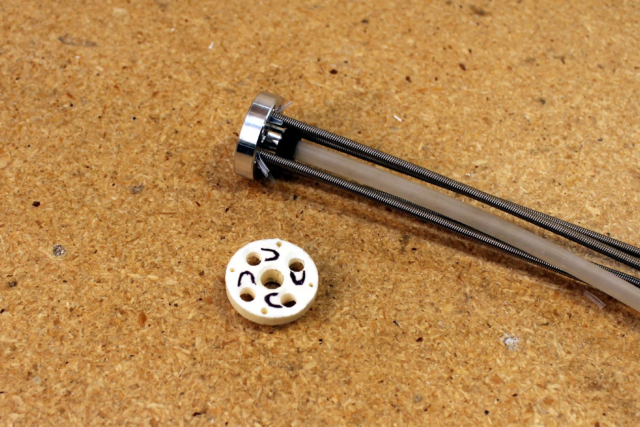
Step 13: Secure Lower End of Polyurethane Tube into Tentacle Base
Feed the spring housings, extending out of the lower tentacle segment, through the clearance holes previously drilled through the base piece. Then, seat the end of the polyurethane tube into the center hole of the base piece. Everything should seat down snugly with no gaps showing between discs and grommets. If the urethane tube is too long trim it with an exacto knife.


Step14: Press-fit Ends of Shorter Cable Housings Into Tentacle Base
Press fit the shorter length of cable housings into the previously drilled capture holes of the cast urethane tentacle base. Use the liner splitting technique discussed before, to prep the ends of the Teflon liner. Once these last four housings are installed in the tentacle base, we should have a total of 8 housings, of approximately equal length, poking out the bottom of the tentacle. They don't have to be exactly equal length, just fairly close.


Joining the Upper and Lower Tentacle Segments
Step 15: Slide the Speedo Cable of Upper Segment Through Urethane Tubing of Lower Segment
Now, feed the speedo cable extending out of the bottom of the upper segment into the polyurethane tubing of the lower segment. It may take some doing to work the speedo cable past the aluminum inserts pressed into the urethane tubing. The bottom end of the upper segment seats down upon the upper end of the lower segment, and a short length of the speedo cable should be protruding from the bottom of the tentacle base.


Step 16: Secure Speedo Cable with Shaft Collar Where It Exits the Base
Find the length of speedometer cables protruding from the bottom of the tentacle base and slide in 1/8 inch inner diameter shaft collar over the speedo cable. Secure it in place with the set screw, and trim off the excess speedo cable with the cable cutters.

Step 17: Trim Excess Length of Speedo Cable
Get in there with the Felco cable cutter and snip off the excess speedometer cable.

The Mounting Flange
This tentacle mechanism is nearly functional. We are now going to mount the tentacle on a flange which will allow us to secure the tentacle to the cable controllers (we have yet to construct). Basically, we want a length of quarter inch aluminum armature wire poking out of the base of our tentacle so that we can orient the tentacle in whatever direction is desired.

While photographing the assembly process, I was taking things apart and putting them back together fairly often. I found it helpful two number all of the holes and cable housings. Being organized does sometimes help.


Step 18: Drill Clearance Holes in Mounting Flange for Housing and Speedo Cable
Basically, we need clearance holes for the cable housings (8 total), a receptacle for the shaft collar securing the end of the speedometer cable, and clearance holes for the ¼-20 bolts we are going to use to fasten the mounting flange to the tentacle base. The eight holes for the housings to pass through should be at least .156” diameter, and the ¼-20 bolts need at least .25” diam clearance. For the shaft collar receptacle hole, I just made a .25” deep, .5” diameter hole with the countersink bit I have been using to chamfer the holes in all the cast parts.

Step 19: Insert Cable Housings Through Clearance Holes
Run the cable housings through the clearance holes in the mounting flange. All the various holes in the tentacle base and the flange should line up. If not, well, you are very special.

Step 20: Bolt Flange onto Tentacle Base
A couple of ¼-20 bolts and nuts should do it.


Step 21: Secure Quarter Inch Armature Wire Into Mounting Flange
For the sake of our little demonstration, I jammed a length of aluminum armature wire into the center hole of the flange. I didn't worry about set screws or anything like that. Ultimately, how a tentacle mechanism gets mounted is entirely a matter of how it is going to be used.

Cutting, Crimping, and Running Cables Through Housings
At the heart of our tentacle mechanism are the cables. Cable actuated systems are very common in animatronics, because they are so flexible, both literally and figuratively. When creating mechanisms that mimic organic movement, flexibility and compliance become very important issues. So, for those who are interested in such things, this is some tasty information to have.
You may be familiar with cables from bicycles, but bike cables and housings tend to be too stiif for use in a tentacle mechanism. With the exception of housings, most of the cable and cable related things I need, I can usually find it at www.versales.com . They carry a lot of rigging supplies used onset for film and television. Specifically for this project, I used the following Ver Sales items:
Microcable #90.0 ( 7x7 , .027” diam.)
Nicopress Copper Stop Sleeves (Crimps) #871-32-B
Nicopress Hand Tool (Crimpers) #17-BA
Felco Cutters (Cable Cutters) #C7
Step 22:Cutting the Cables
The tentacle mechanism measures a little under 3 feet long from one end to the other, so let’s cut each of the eight cables to 48 inch lengths. The first thing to keep in mind about cutting cables is that the cables are of high carbon steel and do require special tools to cut effectively. I strongly recommend that you get the Felco Cable Cutters from Ver Sales mentioned above. The trick to cutting the cables without them fraying at the ends is to anneal the cables with a micro torch before you cut them. Only a small area of the cable needs to be heated for this to work.


Crimping the Cables
With the Nicopress Hand Tool (a.k.a. crimpers) from Ver Sales, crimp a Nicopress Copper Stop Sleeve (a.k.a. crimp) onto the end of each of the eight cables. Insert the end of the cable into the copper crimp and squeeze it real good with the crimping tool. When you crimp down on the crimp, hold it tight for a second or so. That way, the copper sleeve bonds well with the cable so it won’t slip. Then, with the Felco Cable Cutters, cut that little crimp in half on the cable. We are dealing with tight space restrictions within this tentacle and half of that crimp is still plenty strong for our purposes.

Itty bitty crimp


Squeeze down for a 2 count to get a good bond


Cutting the crimp in half is SOMETIMES a good idea


Nice, low profile that will fit inside the tentacle
Step 23: Feeding the Cables Through the Tentacle Mech
O.K. the time has come to cable the tentacle mechanism. Start at the tip if the tentacle and run four lengths of the steel cable through all the discs and down through the spring housings. It is work that requires one to be methodical and have a sure hand. Periodically, the ends of the cables will fray when being strung strung through the little holes in the discs. When this happens, anneal the frayed end of the cable with a micro torch and trim off the offending bit of cable with the cable cutters, and continue on. Once the upper segment is cabled up, continue on with the lower segment. It’s pretty much the same deal.

Tweezers = tiny fingers


The ends will sometimes fray. Anneal, snip, continue.


Feeding the cable down through the lower segment


The cable is all the way through the housing.


The pull test

It moves!

The upper segment is now cabled

Start cabling the lower segment


Cabling complete
Wrapping Up the Tentacle Assembly
Alright, at this point the tentacle is assembled and all the cables are installed. Now we need a way to control the tentacle. In Part 5 we will cover cable controllers.