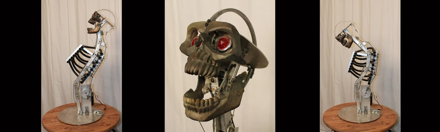

Tentacle Update: Turkey Neck
/With Thanksgiving just the corner, I figure that it is an excellent time to describe how the tentacle mechanism I wrote about, back in July, was adapted for use as an animatronic turkey neck.
A few weeks ago I received a phone call, from someone I frequently do work for, inquiring about an animatronic turkey puppet that needed a mechanized head and neck. The schedule was tight and a system was needed that would provide lots of expressive movement and it needed to be operable by a single puppeteer. “I have just the thing”, I told him, and in very short order I was able to send him images demonstrating how an already existing tentacle mechanism can be modified into a turkey neck. Here is an overview of the process I went through to modify the 2-Stage Tentacle Mechanism into a turkey neck.
000_Tentacular Turkey Neck

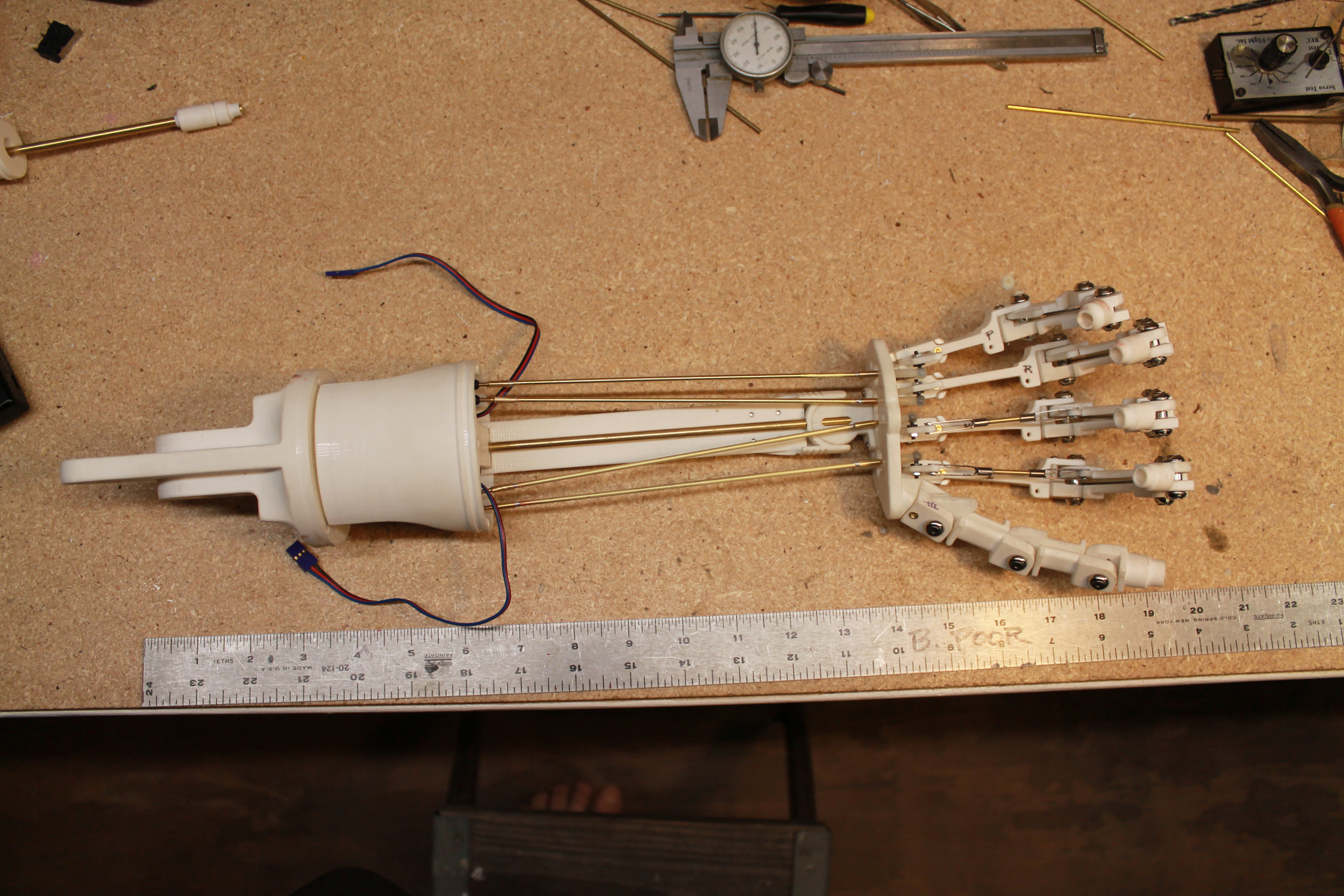
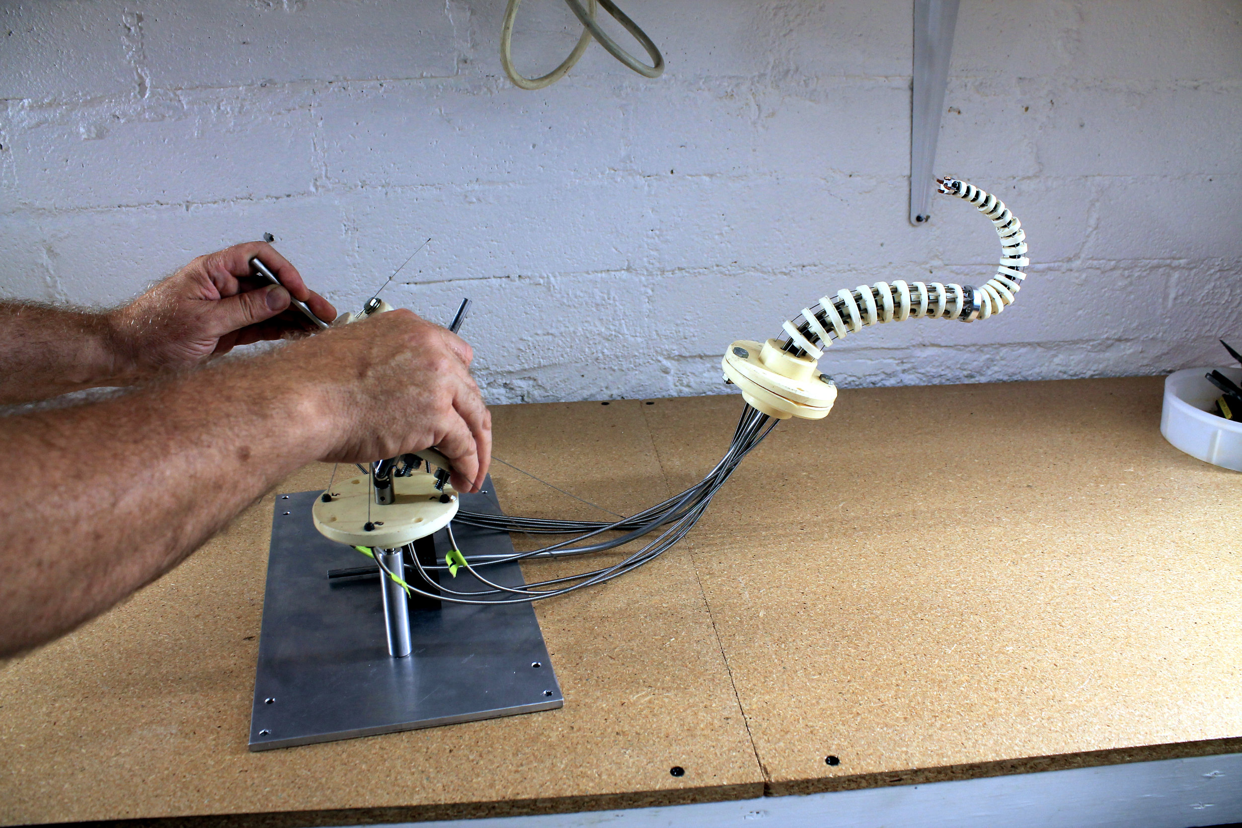
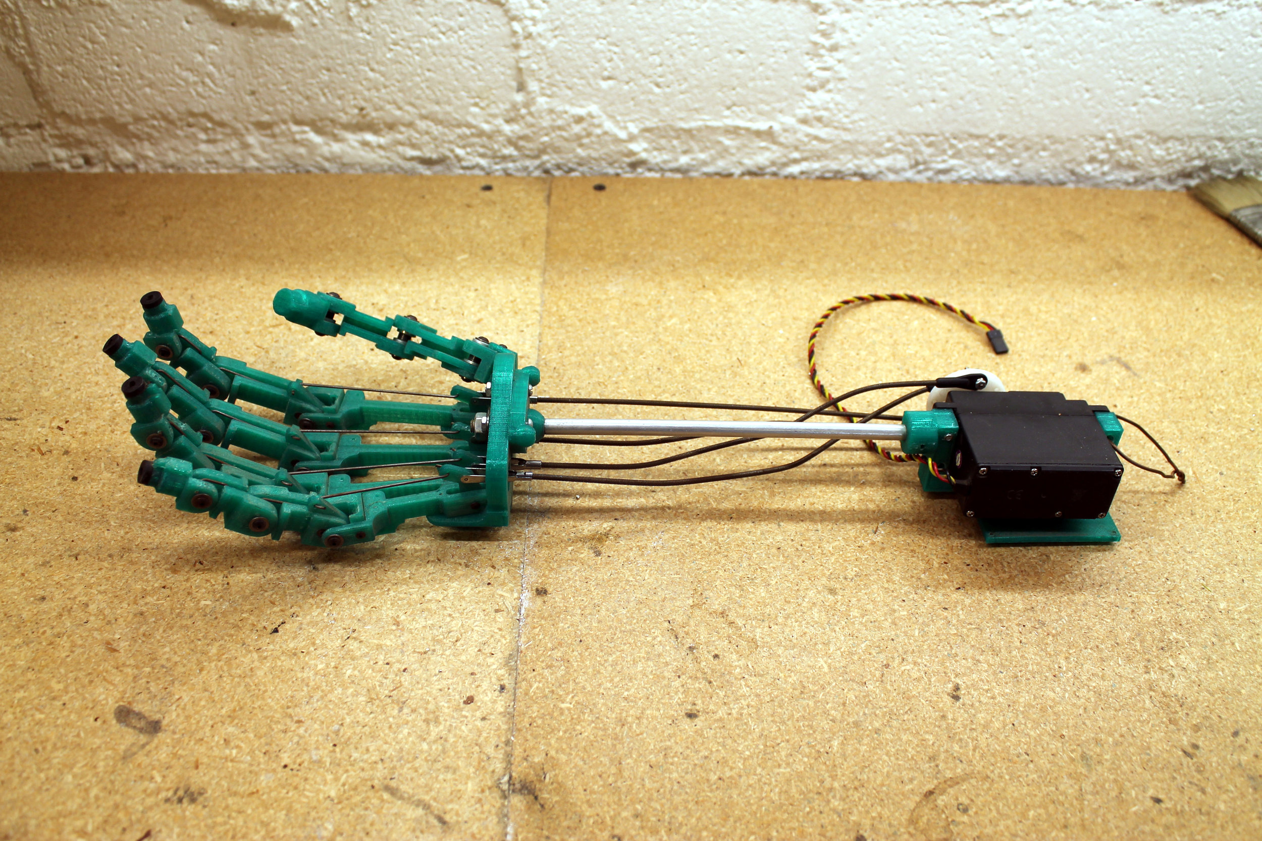
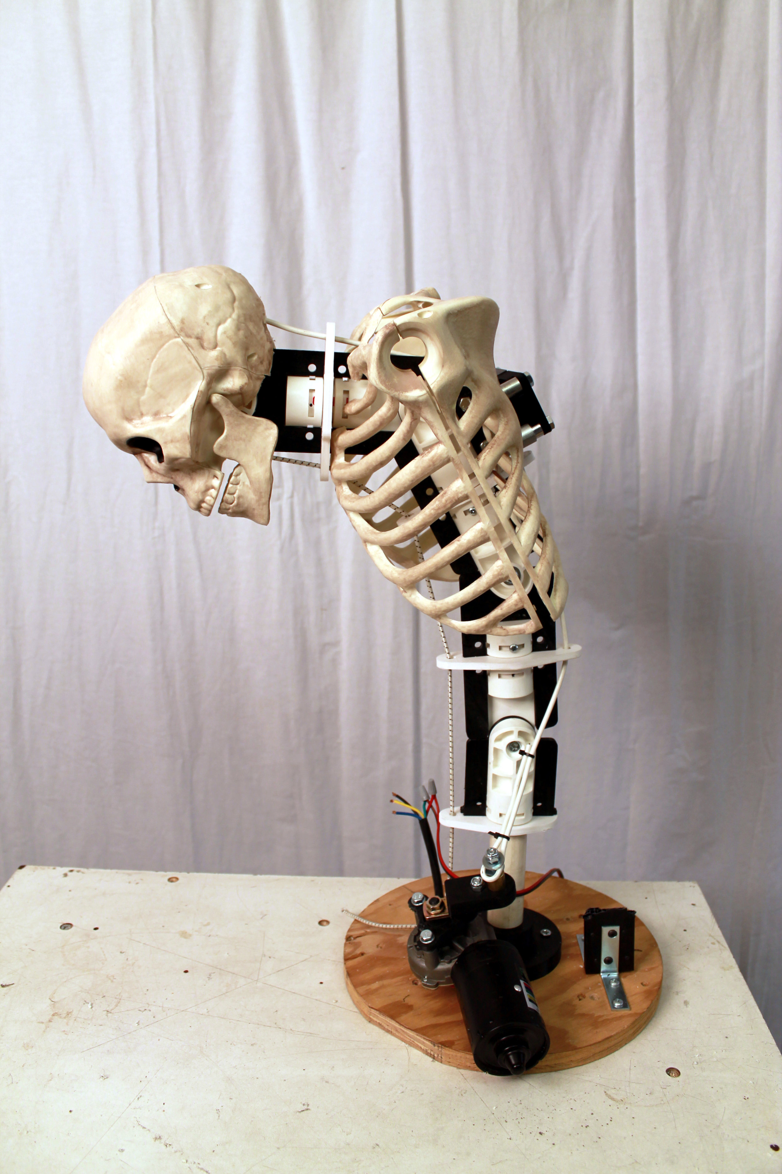
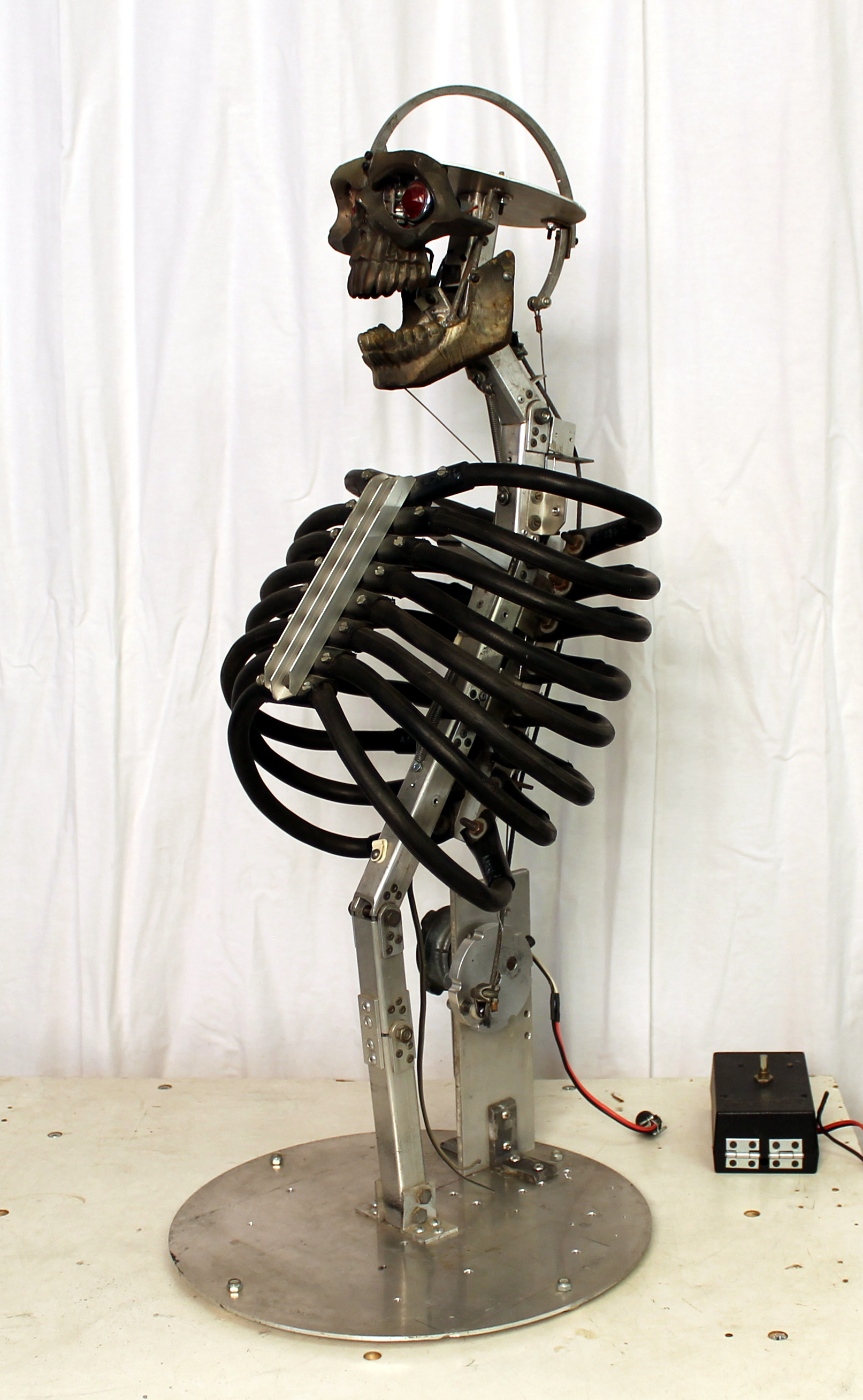
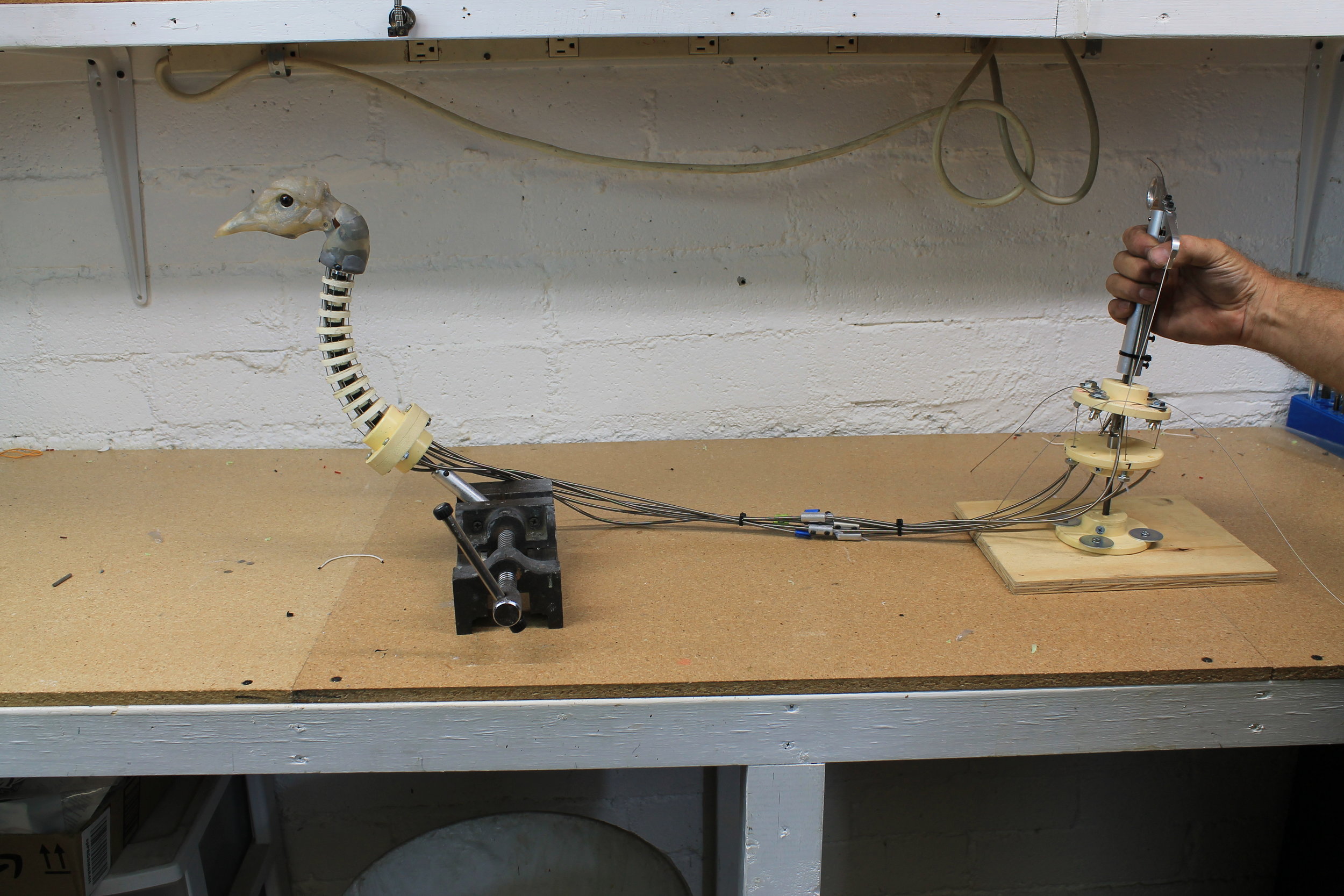
001_The 2-Stage Tentacle Mechanism prior to modification
The puppet in question needed to operated by a single puppeteer. One arm of the operator passes through the body of the puppet from the rear, supporting the base of the neck and providing gross movement to the entire body of the puppet. The other arm of the puppeteer would be used to operate a single cable controller connected to the mechanized head and neck.
So, to adapt the 2-Stage Tentacle Mech, the top stage needed to be removed and replaced with a head. Pretty straight forward.

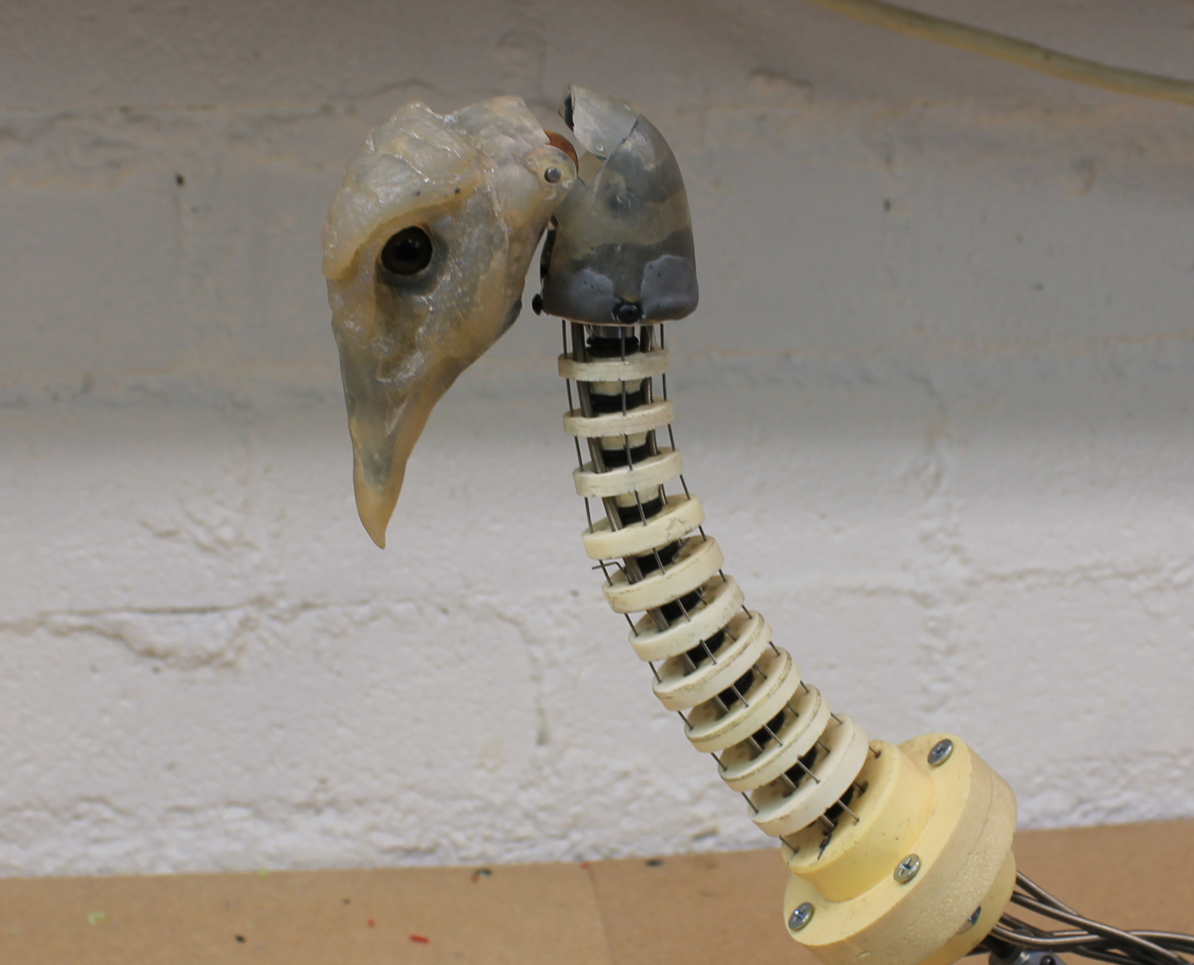
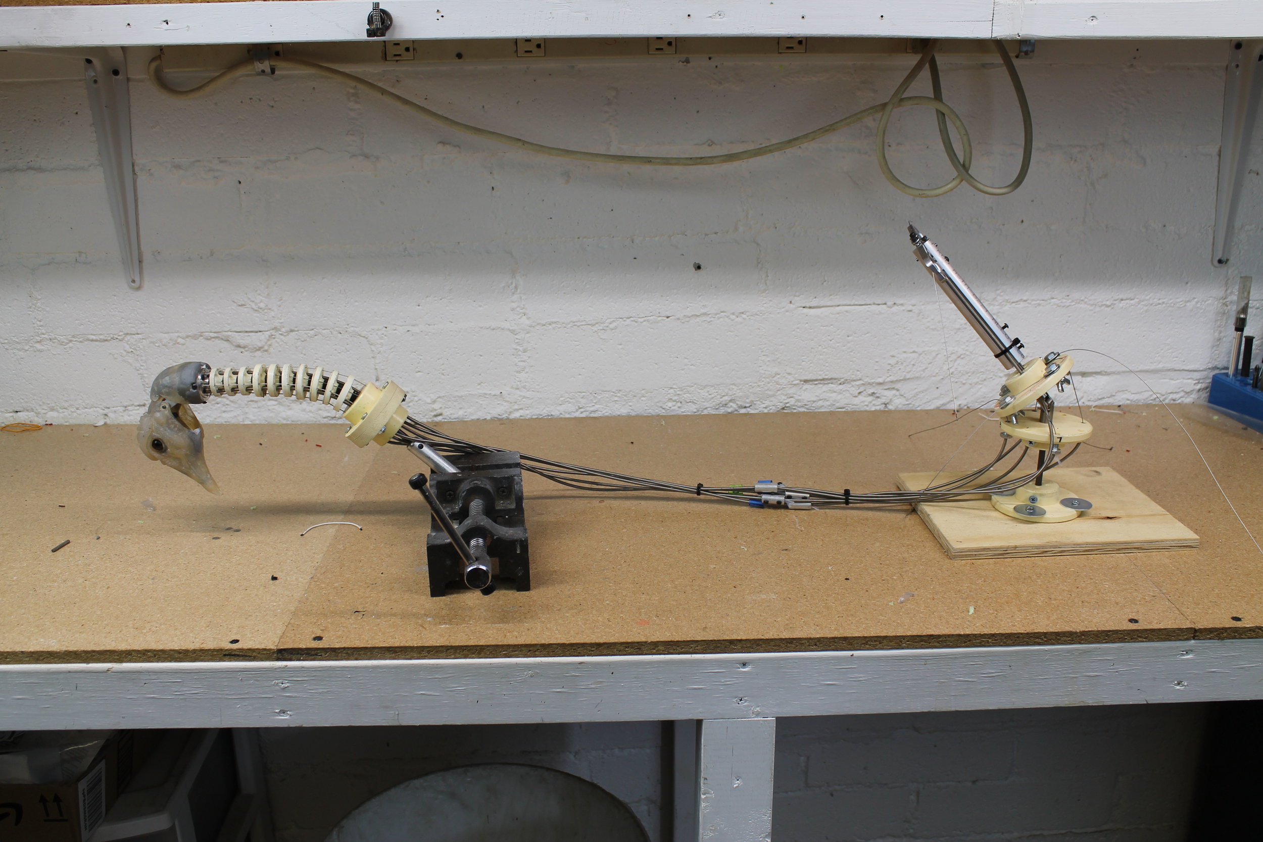
002_Initial image presented to illustrate the concept
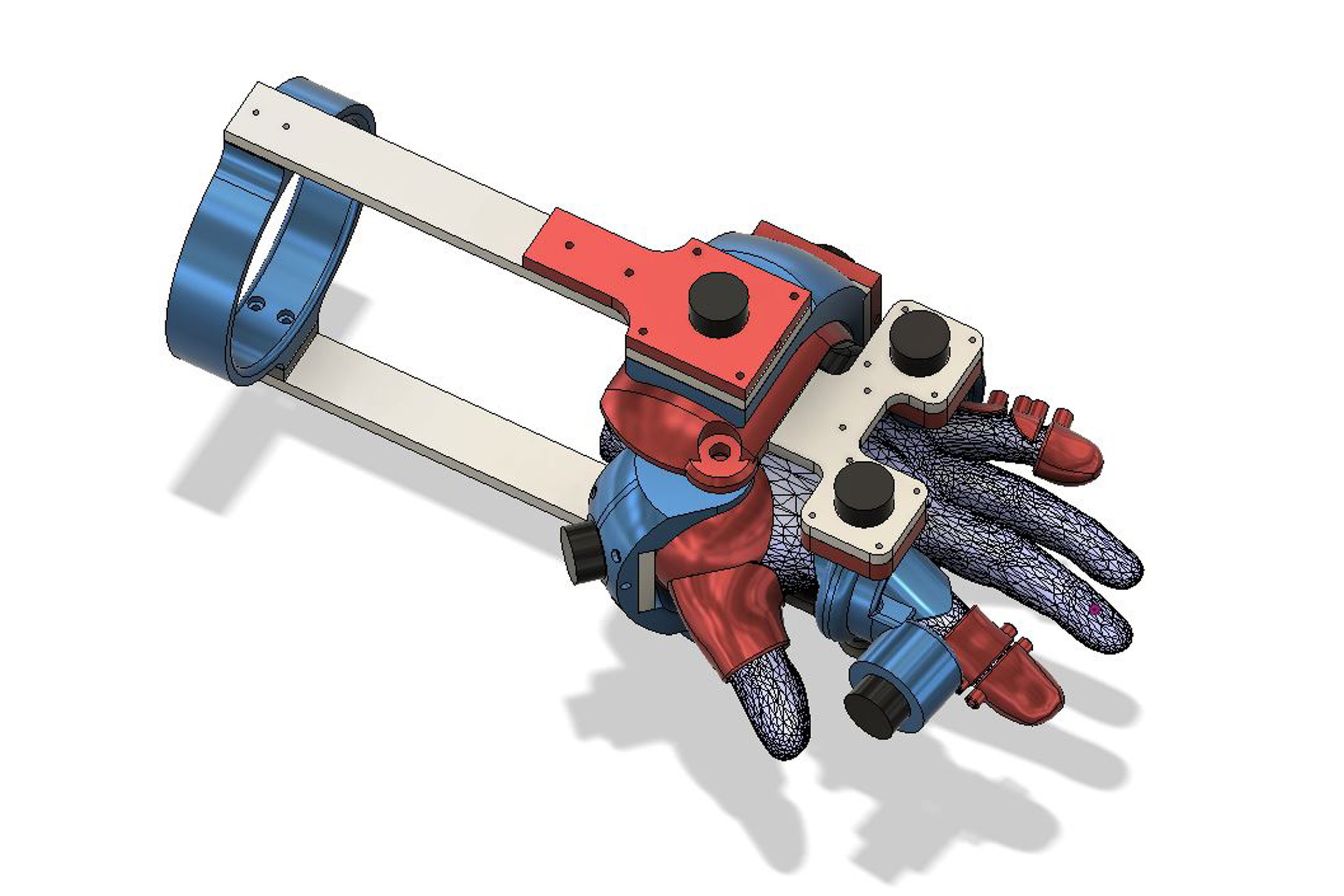
I snapped a quick photo (see image 002) to demonstrate the basic concept. I also created a CAD model of the mechanics and laid it over a photo of a turkey head to further illustrate the idea (image 003).

003_CAD model further illustrating the approach
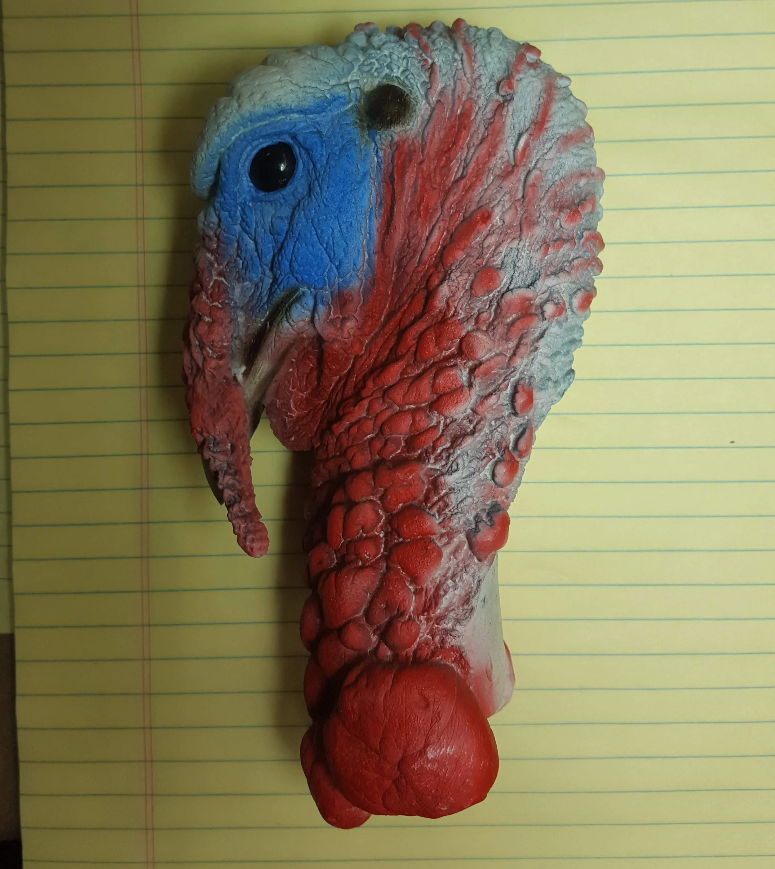
004_Turkey head taxidermy form
TIL (today I learned) the dangly bit hanging off of the turkey’s face is called a “snood”.
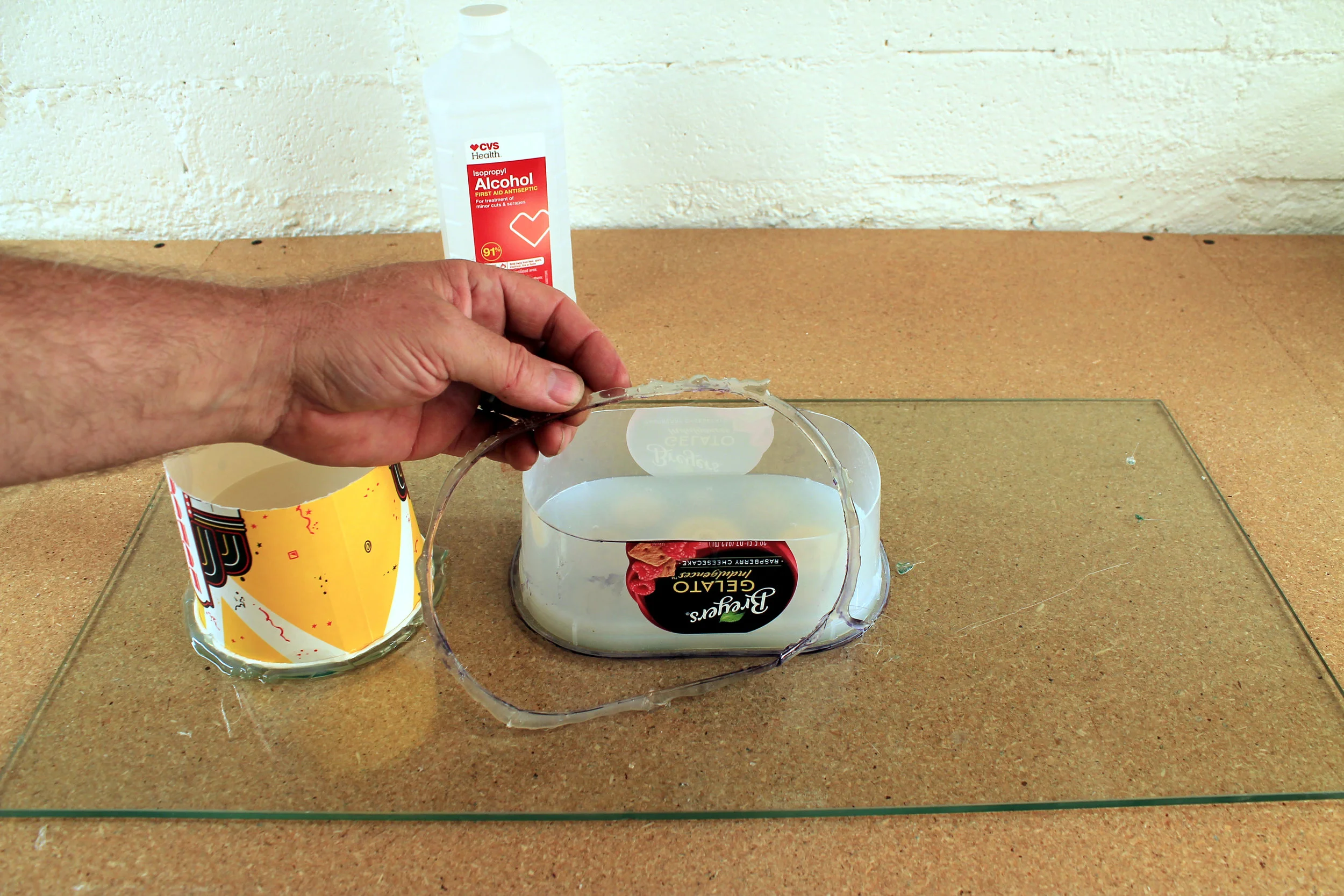
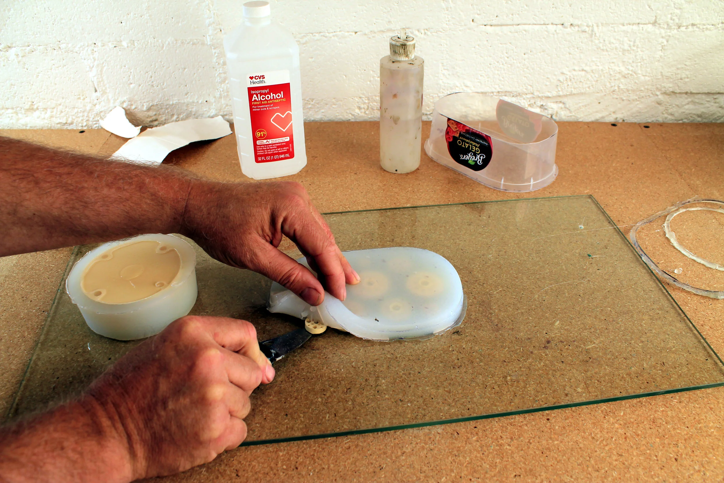
A pre-painted taxidermy turkey head was obtained and a mold was made. It was decided that all the red areas of the turkey would be of .25” thick silicone. The head from the ears forward would be a fiberglass shell, except for the snood, which would also be cast silicone. A core for the skin molding process was made by carving down a hydrocal casting of the head. All the soft bits were carved away to a depth of .25”, representing the areas to be of silicone. The remaining parts of the hydrocal head were left unmodified.

005_Hydocal casting being modified to serve as the core for the skin mold
After the modifications to the hyrocal skin core form were finished, I handed it off to the mold maker. I then turned my attention to designing the head mechanics.
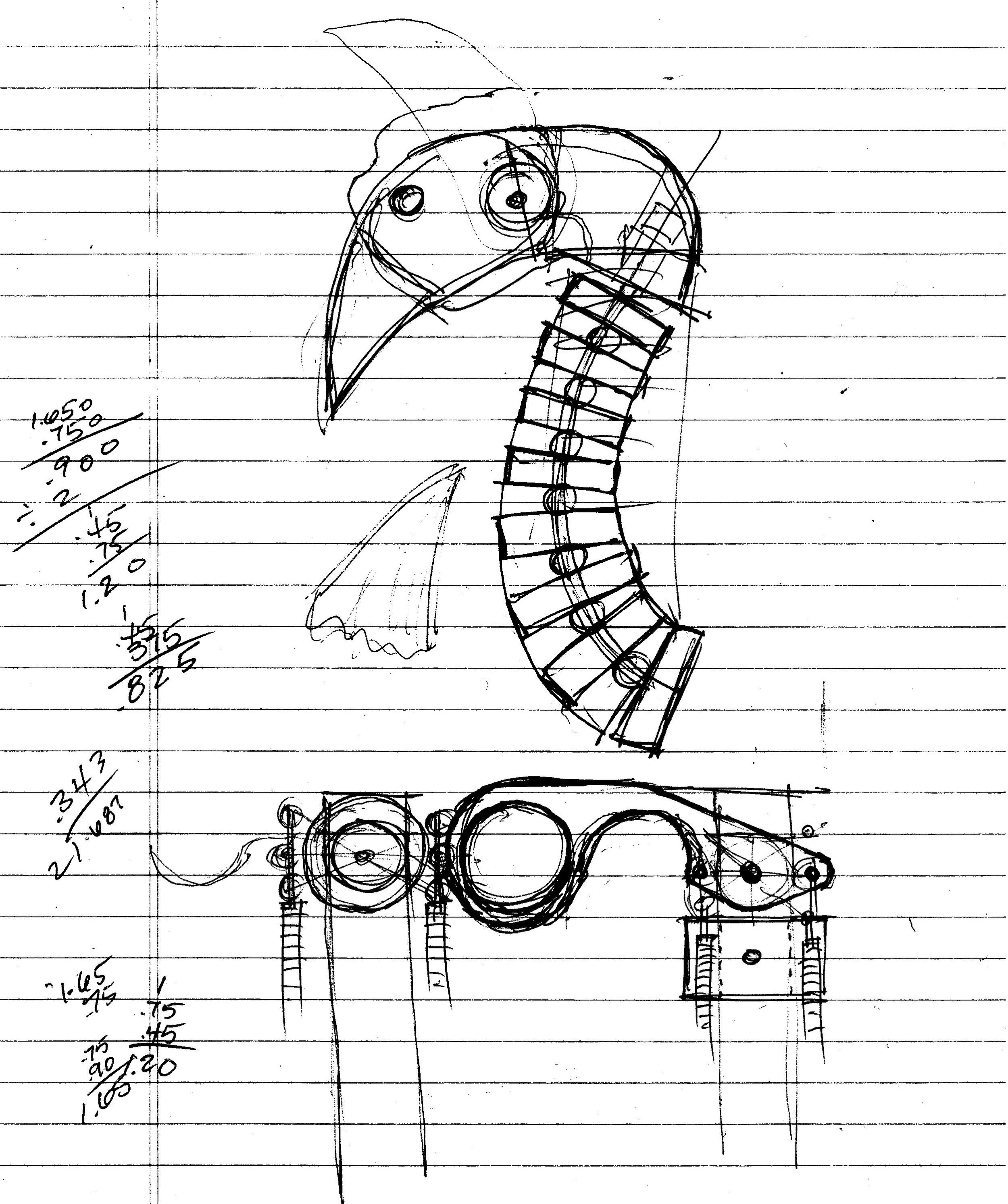
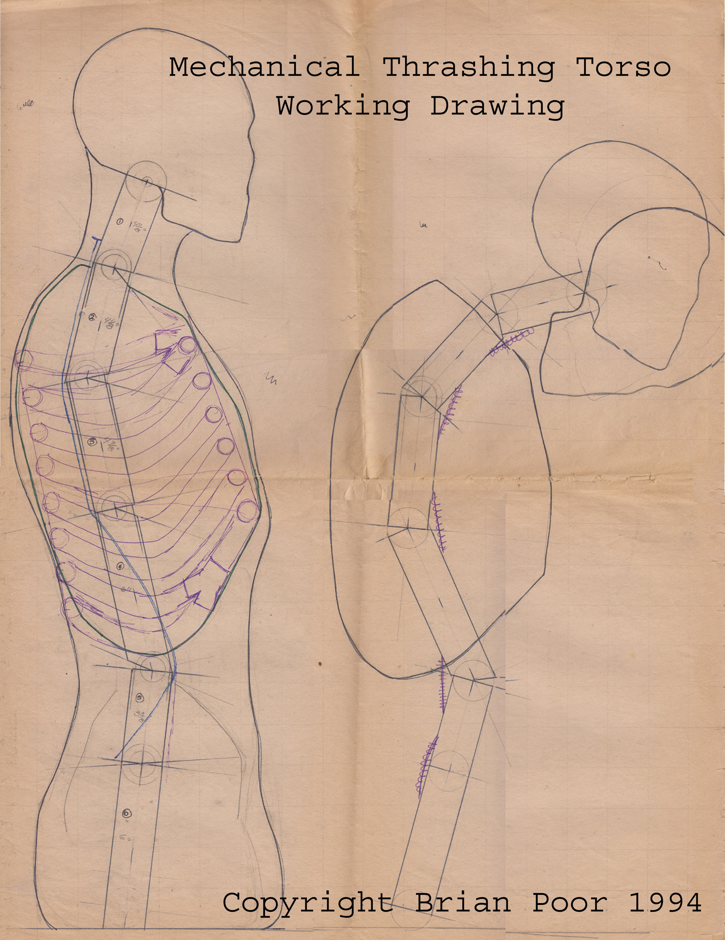
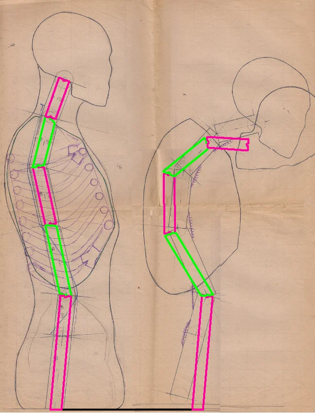
006_Sketches of the mechanics
I always start with a quick sketch to help establish things like what moves and how far. Then I move onto the computer to finalize the mech design in a CAD program. Fusion 360 from Autodesk is now my CAD program of choice.

007_CAD model of the head mechanics
I will spare you the gorey details about the design of the turkey head, but here are a few things I try to keep in mind whenever I design a mechanism:
Keep it simple. Too many complicated parts means it takes longer and is more expensive to build. I sometimes have to stop and count the individual parts I am coming up with just to keep myself from going off the complicated end.
Don’t over build. Make it only a little bit stronger than it needs to be. Lightness counts, especially when it is to be mounted on the tip of a cable controlled tentacle.
Keep things modular. If one part isn’t what it needs to be, be able to quickly remake or modify the part without having to fuck with the rest of the system.
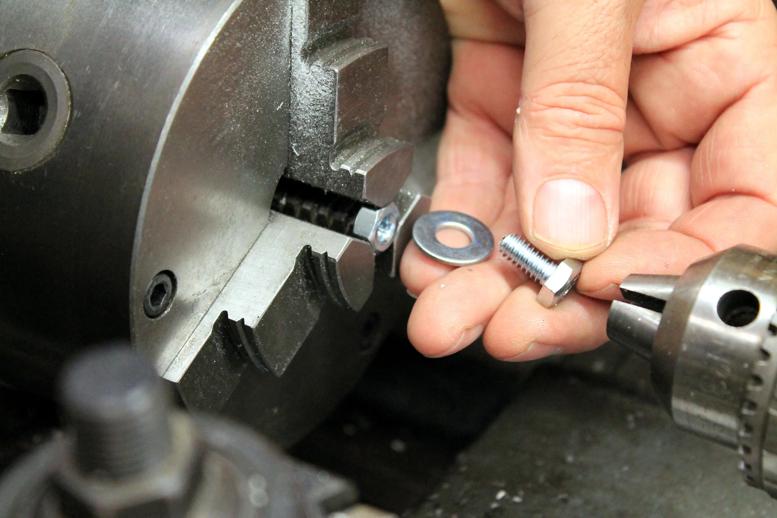
Use the same sized fasteners everywhere. That way the chance of drilling a hole incorrectly is reduced and assembly is simplified. 4-40 screws were the screws of choice for this project.
Keep in mind that fiberglass head shells need to be mounted to the mechanism. Placement of screw holes and gluing surfaces need to be anticipated and provided.

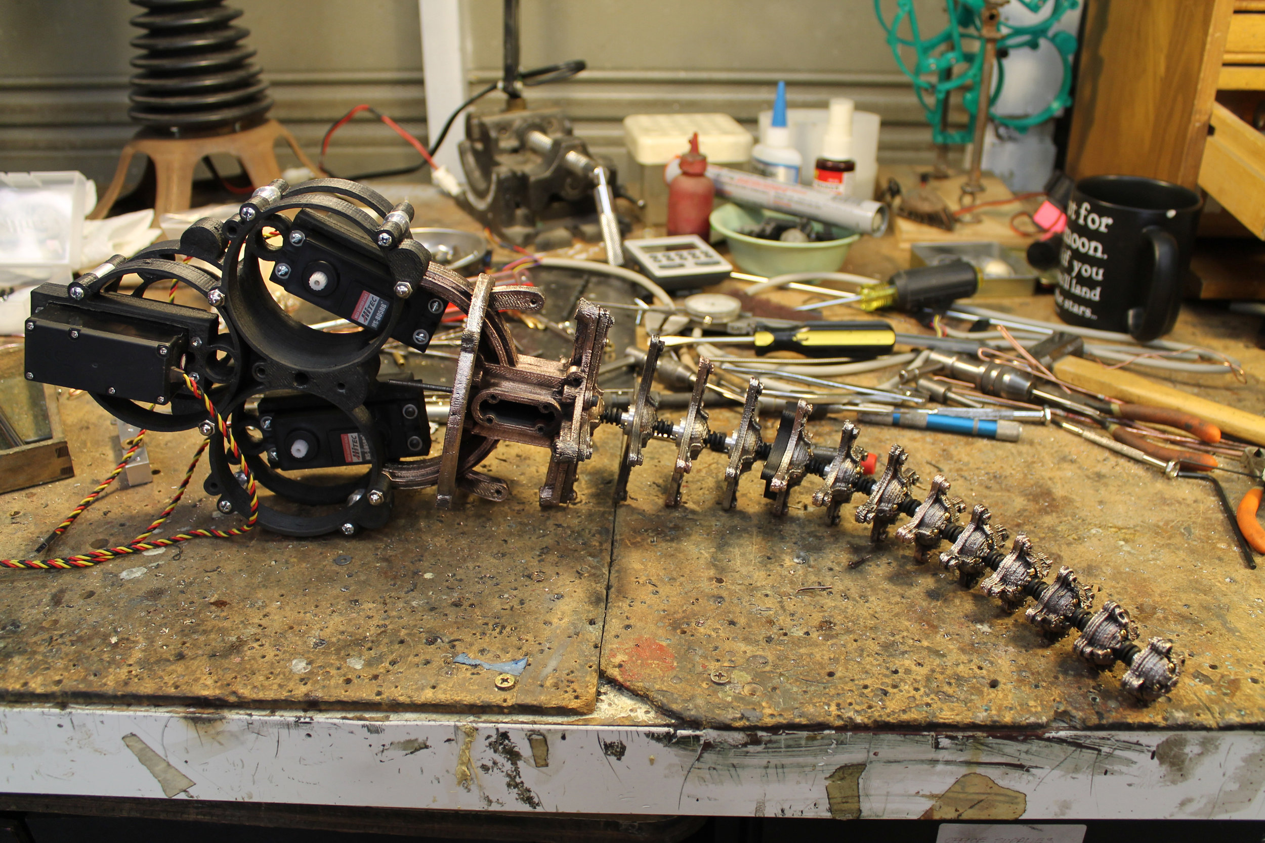
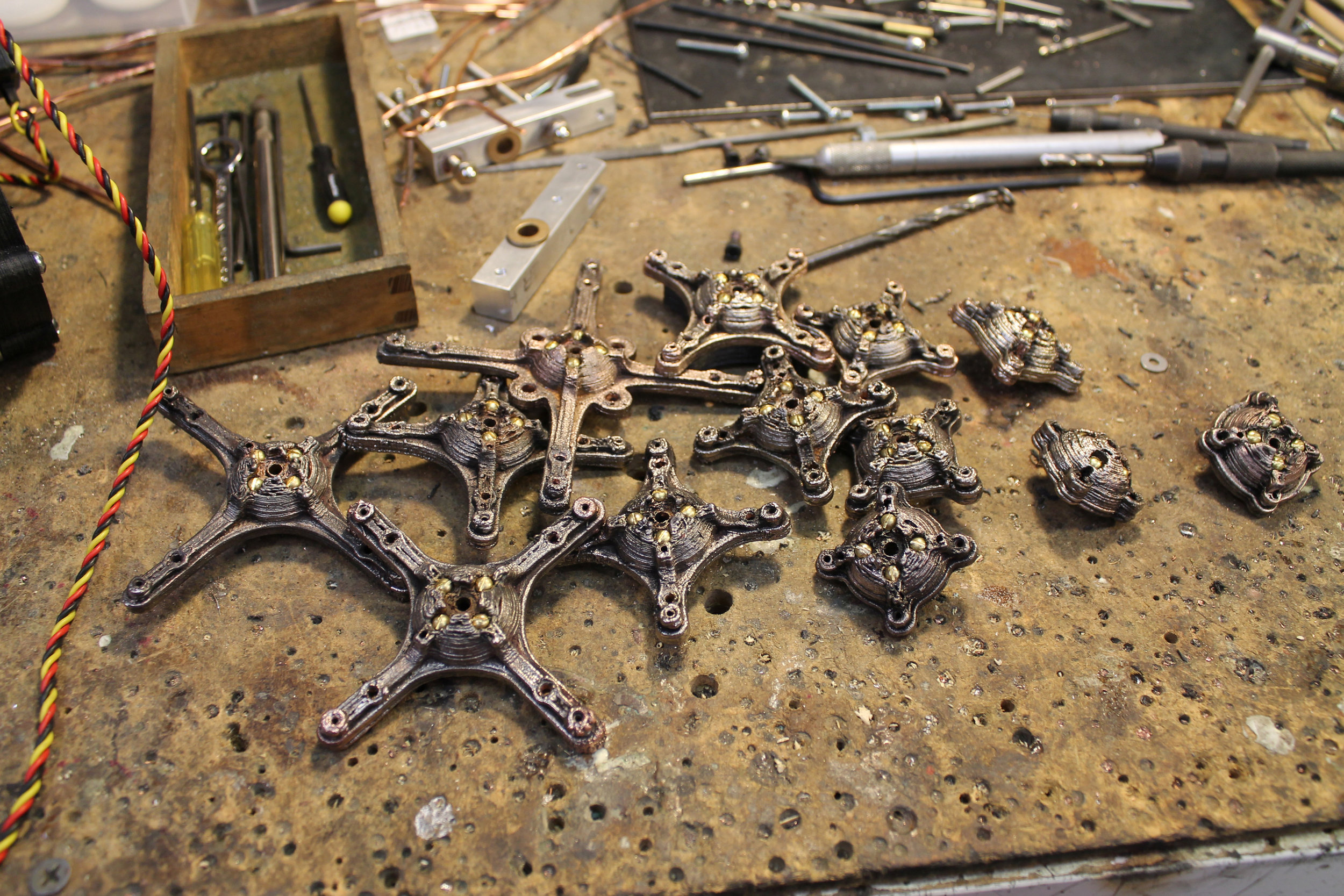
008_Turkey neck mech
With only some minor modifications, the tentacle mechanism has been converted into a very functional animatronic turkey neck.

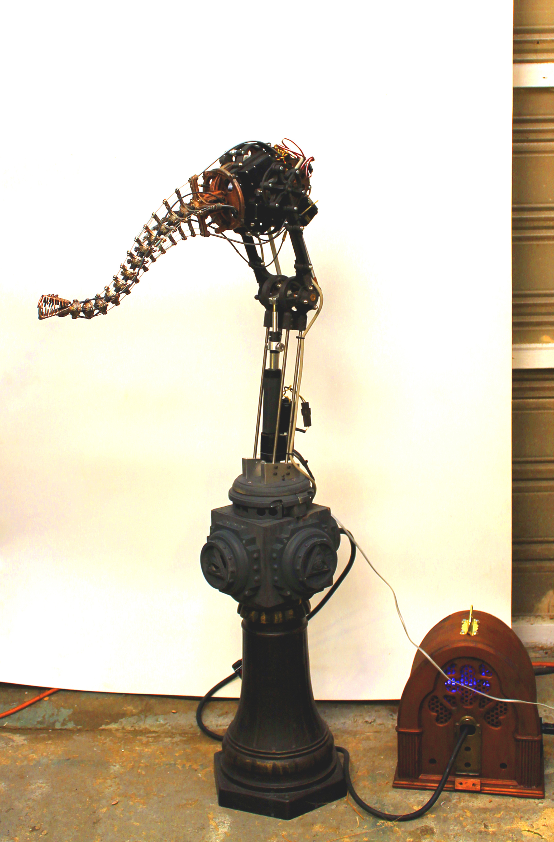
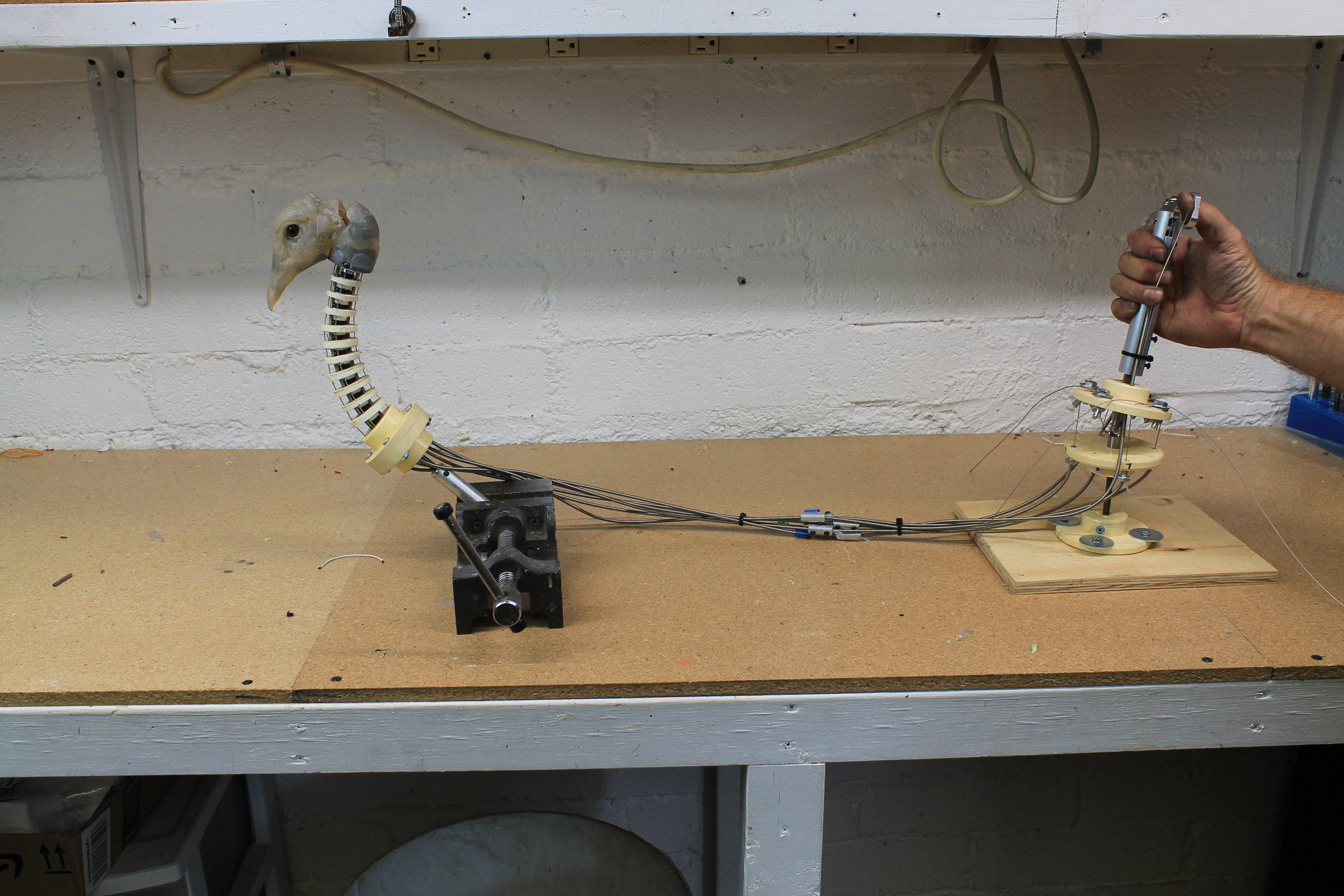
009_Testing the cable actuated mechanics
Over the years I have developed a healthy paranoia about mechanisms not doing what they are meant to do, and I like to conduct little tests along the way. Frankly, cable actuated tentacles are not very good at supporting weight at their tip. It’s just the way the physics work. So as soon as I got the this thing cabled up and the head mech installed I had to make sure the silly thing was going to work. The test was successful and I moved onto installing the fiberglass head shells.

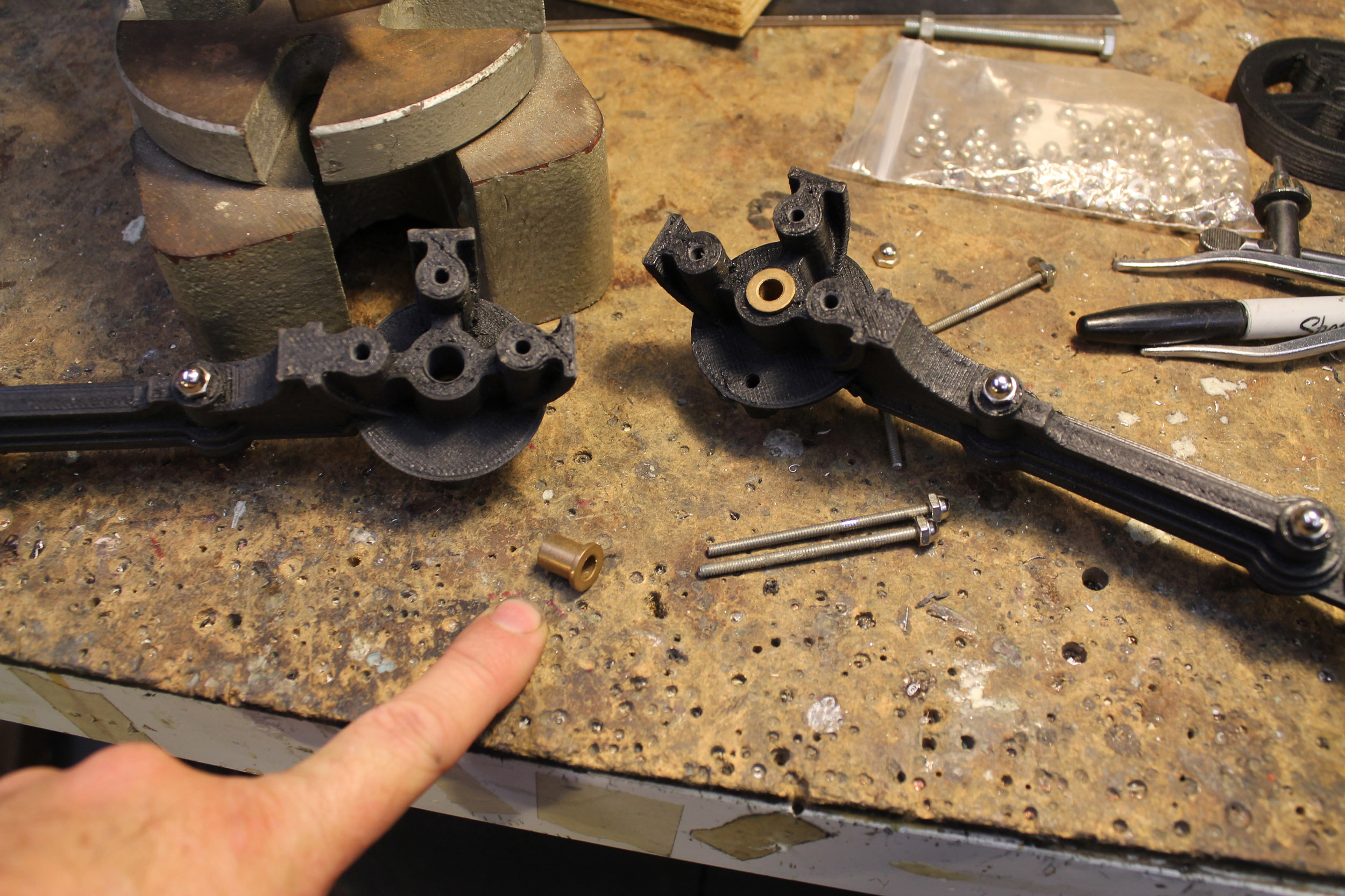
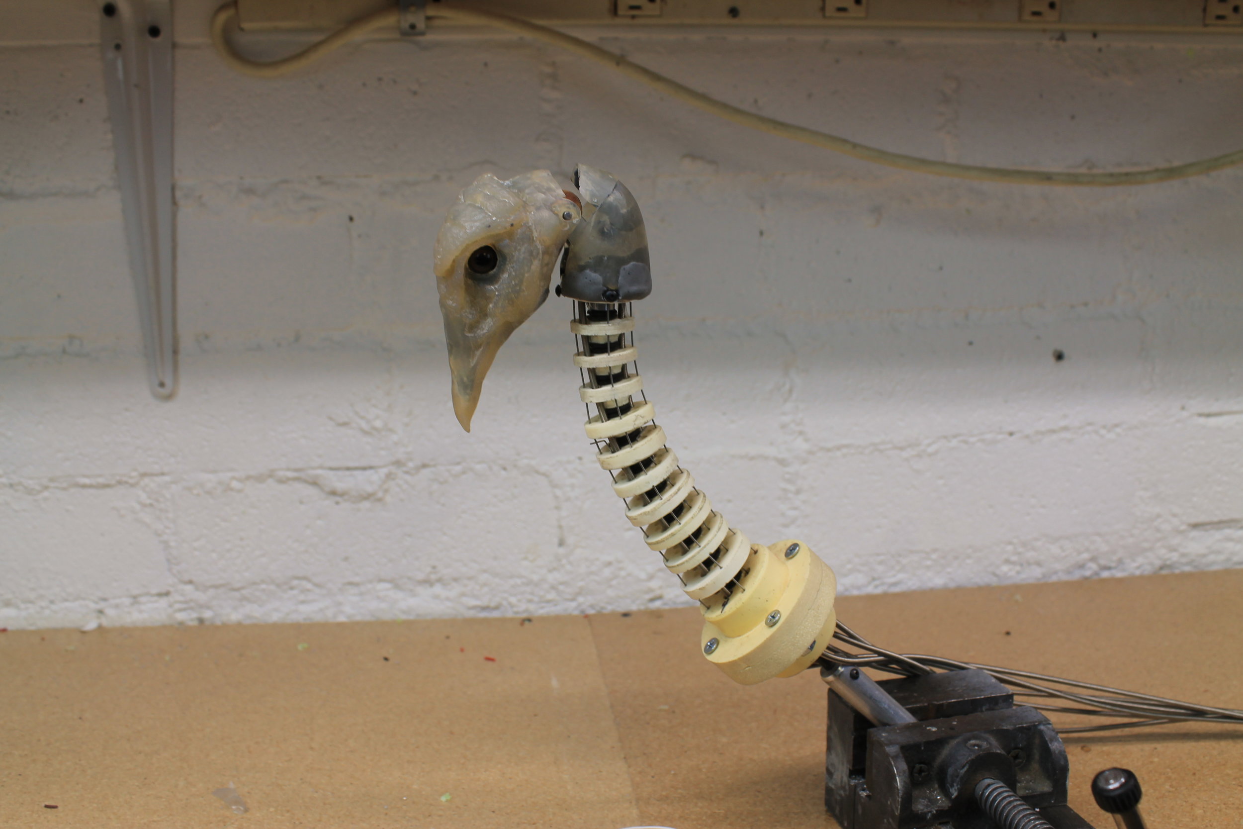
010_Head mech detail
A quick rundown of the head mech:
A clevis is mounted at the end of the neck tentacle
A cable actuated bell crank pivots within the clevis
A pair of struts extend off of the sides of the clevis, to support the head plate
The head plate pivots between the two struts
A rigid link connects the bell crank to the head plate
I purposely included technical jargon like clevis and bell crank. It does help to use the precise technical terms for things when trying to describe a mechanical system. That being said, I didn’t know any of these terms when I started my career in animatronics and picked up the jargon along the way. I may well be using these terms incorrectly; my degree is in Studio Arts, not Mechanical Engineering.
011_Head shell detail
The fiberglass head shells were then mounted to the mechanics. Mounting shells is an art. The shells are there to support the skin and act as an interface between the mechanics and the flexible skin material. The job of the animatronics mechanic is basically to move skins in a convincing way. The shells need to mounted securely and in such a way that the skins gets stretched and compressed in a naturalistic way without funky wrinkles. Mounting shells is an art.
012_Fiberglass head and neck shells installed (head full down)
Move test time, once again.
013_Head full up
I do believe it is going to work
014_Gravity having its way
It is now ready to handed off to the art people to cover with silicone, foam, and feathers.
Here is the final video test of the Turkey Neck Mech, ready to install. Happy Tentacular Turkey Day!