

WWoT (Part5) Cable Controllers
/Squash Plate Cable Controller

Squash Plate Controller Operation
The tentacle mechanism functions on the principle that one cable on one side gets longer while the cable on the opposite side gets shorter. The squash-plate controller works exactly the same: one side the cable gets longer, other side the cable gets shorter.


The Basic Components

Universal Joint
An affordable universal joint suitable for use in this project can be found online at McMaster Carr:
www.mcmaster.com/#6445k1/=1dte6o7
The u-joints actually shown in the photos is this one, www.mcmaster.com/#60075k77/=1dte87j , and it is surprisingly pricey (about $50 each). They were in my stache of left over parts from jobs long over with. This u-joint had a predrilled set screw hole while the less expensive one above needs to be drilled and pinned to the shaft. Easy and expensive or cheap and requiring more work, such are the choices in life.
Step 1: Make the U-Joint Thingy
Two controllers are needed, each with a universal joint. Cut four 6” lengths of .25” steel rod and secure them into the two u-joints. If you have the expensive u-joints, set screw them. If you have the cheap ones, drill and pin them; or solder them, or weld them (but don't go crazy with the heat).

The Plates
Finishing the Cast Urethane Plates on the Lathe
The cast urethane plates for the squash-plate controllers will probably be fairly flat after the casting process, and the .25” diameter center hole needs to be drilled through fairly straight, which could be accomplished with a cordless drill and a steady hand. I, however, chucked up the plates on my lathe, faced off the flat surfaces, and precisely drilled the .25” center hole, dead nuts straight and centered, because it just takes less effort on a lathe.
Drilling Holes in the Plates
The cast urethane plates need to be finished by drilling holes in them. Let’s take a look at the finished product so that we know what holes get drilled where and why.


Here is a run down of the important features of the squash plates:
Top Squash Plate:
The top plate of the squash-plate controller has four clearance holes for .5” long ¼-20 hex head bolts with two washers and a nut on the upper side. This hardware is for capturing the ends of the cables coming from the tentacle. There are four additional 1/16th inch holes, equally spaced between the .25” clearance holes. These holes are pass through holes for the cables. It is important that these holes be equally spaced from the center of the squash plate for the controller to work properly.
Bottom Squash Plate:
In the bottom squash plate there needs to be a way to terminate the cable housings from the tentacle mech. To accomplish this I used ferrules made from ¼-20 bolts. To secure the bolts in the plate I drilled and tapped ¼-20 holes. What’s a ferrule? Basically, I drilled a hole in a metal bolt to capture the end of the cable housing, rather than drill a capture hole in the cast part. The modified bolt/ferrule is then held in the cast part in the threaded hole. It’s a very strong connection for the end of the cable housing.
Had I been thinking, I could have eliminated the need to drill more holes by using 5/16-24 hardware and just tapped the .25 in holes that already existed in the cast parts. Sometimes I work faster than I think.
Base Plate:
This plate needs is a set screw to hold a .25” steel rod in the quarter inch center hole. I used a 10-24 machine screw because the threads are large enough to be used in cast urethane parts. Finer threads have more of a chance of stripping out.
Drilling the Plates

The upper squash plate needs four holes drilled for the ends of the cables to pass through. The lower squash plate needs four holes drilled that will be threaded to accept ¼-20 screws. We are going to do this by using the .25” diameter holes already in the plates as drilling templates.
Step 2: Align the Plates
The squash plates need to aligned so that the .25” holes are offset from each other by 45 degrees. The existing holes will serve as a guide so that the new holes can be drilled accurately using a cordless hand drill.

Step 3: Pin the Plates Together
Use a piece of .25” diameter rod to pin the upper and lower plates together so that the holes are 45 degrees out of alignment from each other.

Step 4: Use .25” Center Drill the Start Drilling Holes (Pilot Holes)
Center drills are typically used in machining processes to accurately place a pilot hole to be drilled through with a regular drill bit. A pilot hole is simply a shallow hole placed where you want to make a bigger hole. Center drills are useful because they are very stiff and the tip won’t wander around before actually biting into the material to be drilled. We are using the center drill to accurately place a series of pilot holes by fitting it into the existing .25” holes in the squash plates. The .25” center drill will drill right down the center of the .25” holes. Drill four shallow pilot holes in both the upper and lower squash plates right between the existing .25” holes. That’s a total of eight pilot holes.


Step 5: Drill the Top Squash Plate
Use the pilot holes to drill four .062” holes through the upper squash plate. Now that we have the hole placements established with pilot holes, this can be done with a hand drill or a drill press. These holes are pass through holes for the ends of the cables coming from the tentacle mech.


Step 6: Drill the Lower Squash Plate
Drill the lower squash plate just like the upper plate, but make the holes .188”. These four holes are to be tapped with ¼-20 threads.

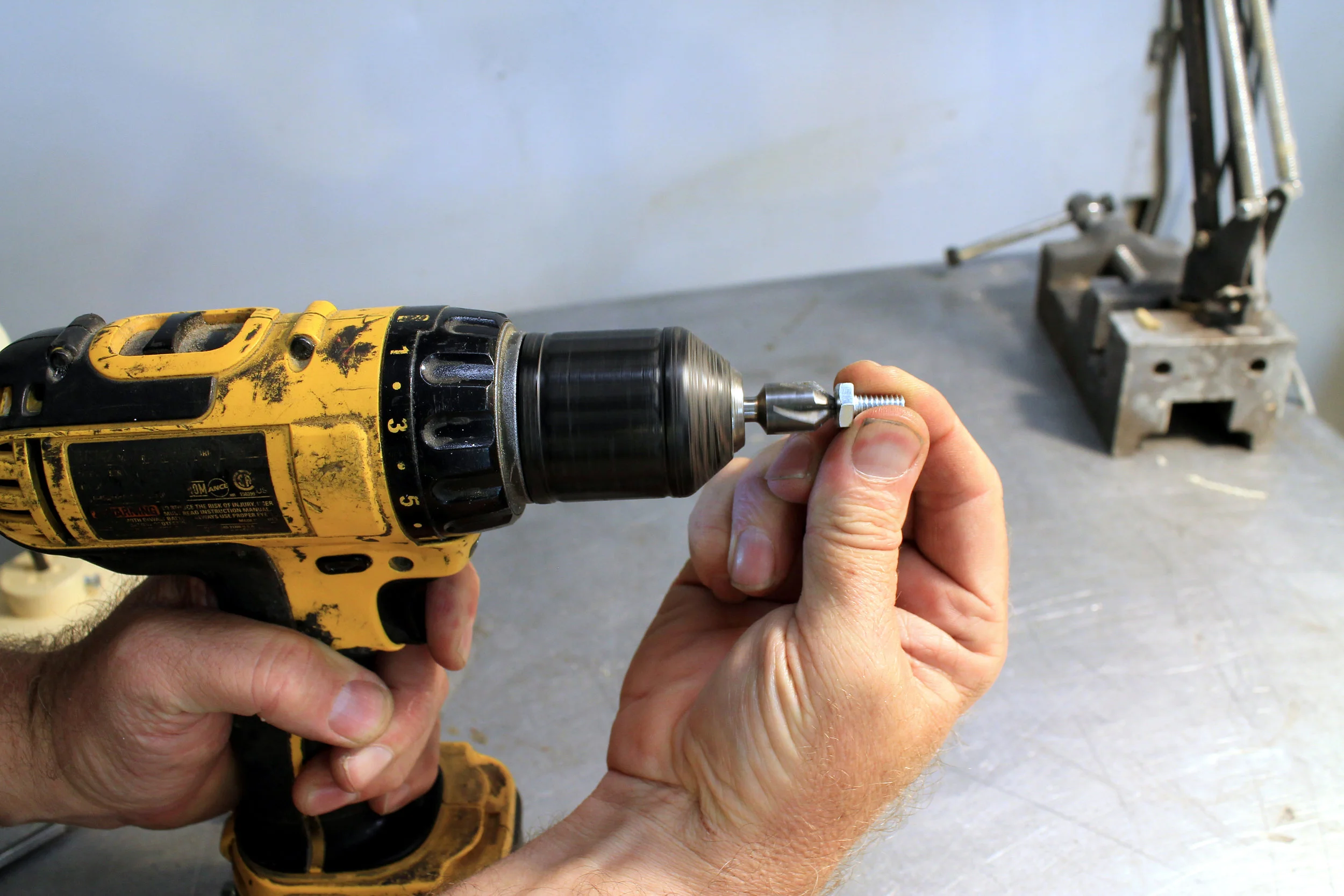
Step 7: Tap Holes in Lower Plate
I used my drill motor to tap these holes with ¼-20 threads. Use a tap handle if that makes you more comfortable.

Step 8: Drill and Tap Plates For Set Screws
Both of the squash plates need to be secured to a .25 steel shaft. A set screw is what is called for to hold things together. To drill the hole I clamped the squash plates in the vice of my milling machine. In this case, the mill serves as a glorified drill press. The same can be done with a regular drill press and a machinist’s vice, or you can just go at it with a hand drill, though I would still recommend holding the plate in a vice. In the photos you can see my set up on the mill. It was a little bit overkill, but I you want super accuracy, this is a way to do it.
I ended up drilling and tapping for a 10-24 set screw, but a ¼-20 screw would work just as well (maybe better). I wouldn’t go too much smaller as we are cutting threads in cast urethane resin and they won’t be very strong.


Controller Assembly
Step 9: Install Set Screw

Step 10: Install the Plates onto the Steel Rod U-Joint Assembly
Slide the upper and lower squash plates onto the steel rods until the butt up against the u-joint. Secure them with the set screws.


Looks good but I almost forgot the ferrules. What are ferrules you ask?
Ferrules, Why They are Your Friend
If you do a search online for ferrules you will discover that a ferrule is a metal doo-dad that slides over another less strong doo-dad to make it stronger. Got it? Me neither. O.K. our controller squash plates are basically .25” thick cast urethane parts and we need to press-fit the ends of our cable housings into them and everything needs to secure and strong. As it is, it aint gonna be secure or strong. That’s why we are going to use ferrules.
I am going to demonstrate how to make ferrules out of ¼-20 hex bolts, and I am going to do it on a lathe. Sorry, but I just don’t know a better way to do it. I’ve looked for off-the shelf alternatives and the best I can find is called a Derby ferrule #620-20900 from www.flandersco.com . It looks like it MIGHT work as a capture for the spring housing IF it is modified by drilling it out to the correct size (.128”), AND you use it in conjunction with the hex head adjuster #620-27264. I don’t know. It might work or it not. That’s why I have a lathe. Flanders is great, by the way: brake cables and housing for motorcycles and stuff like that. Too heavy for use in tentacles but good for bigger cable controlled projects.
Making Ferrules
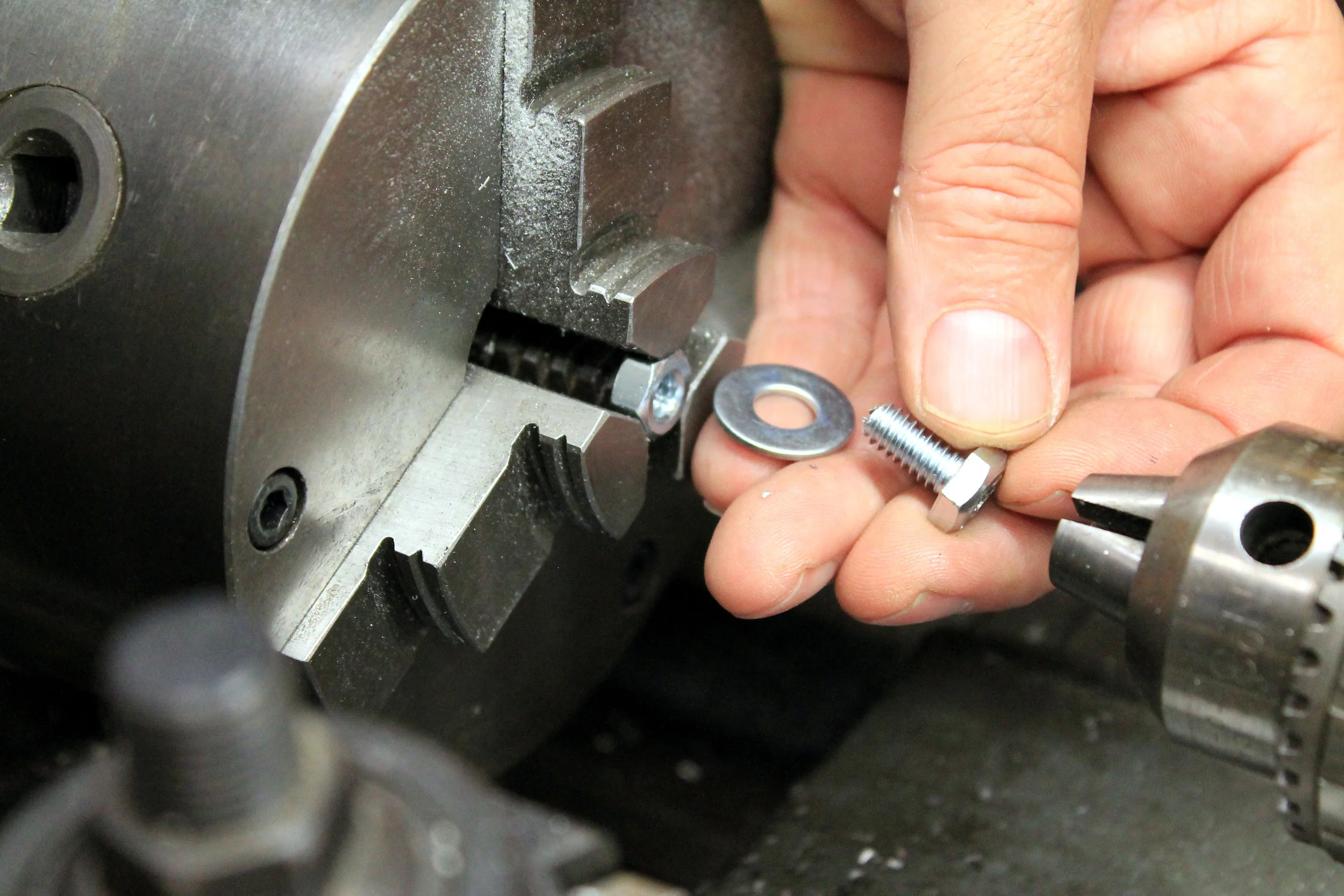
Step 11: Mount a ¼-20 Hex Bolt in the Lathe
Grab a ¼-20 hex nut in the jaws of the lathe chuck. Then thread a .5” long ¼-20 hex bolt into the nut. A washer between the nut and bolt will help to keep everything held straight and true.
Step 12: Drill Out the Hex Head Bolt
We are using .5” long hex bolts, so we need a .128” diameter hole drilled to a depth of .375”. Drill in from the head, obviously. Then drill the rest of the way through the hex bolt with a .062” drill. Drill eight ferrule bolts. Then chamfer the the holes real good so there are no sharp edges.


Step 13: Install the Ferrules
Thread the finished ferrules into the ¼-20 threaded holes, as shown.


Step 14: Install Cable Capture Screws
There needs to be a way to secure the ends of the cables on the upper squash plate. In each of the four .25” holes in the upper plate, put a .5”long ¼-20 hex bolt, two washers and a nut to secure them. The cables will be captured between the washers.


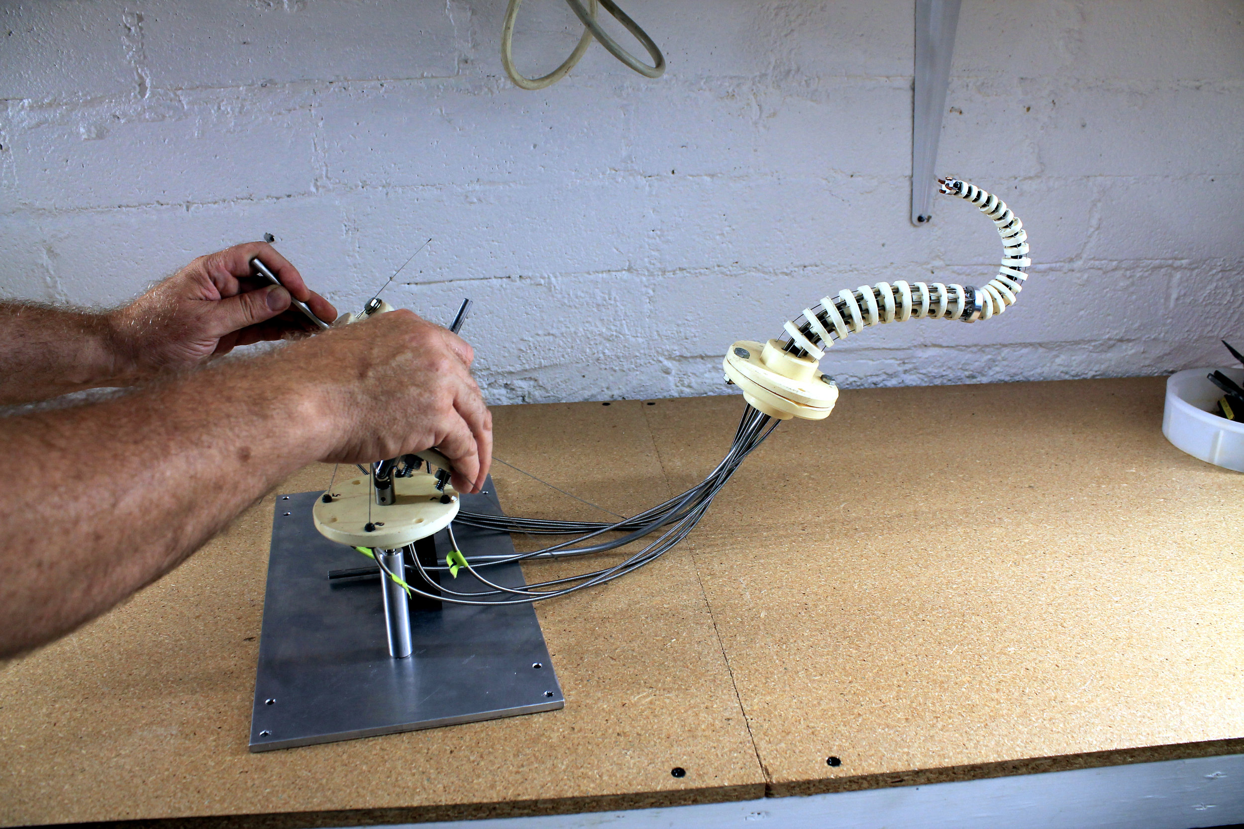
Step 15: Secure the Controllers and the Tentacle to a Base
The controllers need to secured to a base plate along with the tentacle. In the photos you can see that I bolted everything to an aluminum plate. A piece of plywood, or even an old wooden crate, would have worked just as well. Use what you got and what is appropriate. I had an aluminum plate. Securing the tentacle to the base plate is a block of delrin with some holes drilled in it. A chunk of wooden 2x4 could have served as well. Do what you gotta do. Just make sure the tentacle is mounted close enough to the controllers that the housings can be inserted into the ferrules.


If your setup looks anything like this you are good to go.
The Joy of Cabling
The last thing to do is to connect the tentacle cables to the cable controllers. Are you as excited as I am? Let’s do this!
I am going grab all this stuff in my little vice so I can flip it up at a better angle for the sake of photography and the crick in my neck.

The trick to cabling tentacles is to get the right cable in the right hole. If you pull back on a controller you want the tentacle to also pull back. Otherwise, controlling the tentacle will just confuse your brain. Other things to keep in mind: lower segment on one controller, upper segment on the other controller, and keep the front/back, left/right cables together. As this goes together it will all make sense.
Step 16: Insert Cables and Housings into Ferrules
Start with the cable that connects to the front of the upper segment of the tentacle. It connects to the rear part of the controller (on the left, in this case). This way, when the controller pulls back, the cable to the front of upper tentacle segment will lengthen and the upper part of the tentacle will pull back. Awesome huh? If it doesn’t make sense when you read this, it will once you start putting it together.
Anyway, feed the cable into the correct ferrule and press in the housing till it bottoms out in the ferrule. Then do the same for the opposite cable. That is, if you do the front cable first, do the rear cable second. Then continue with the side-to-side cables. Don’t worry about connecting the cables yet, just get the housings press fitted into the appropriate ferrules. Do this for both the upper and lower segments. Be prepared to have to stop and redo your work occasionally. I almost always brain-fart my way through this process.


Step 17: Secure Cables to the Upper Squash Plates
Thread the cables though the little holes drilled in the upper squash plate. Then, while holding the controller handle upright, pull a cable between the washers on the nearest bolt. Pull the cable only enough to move the tentacle into a “neutral” position (or straight up). Don’t worry about getting it perfect, there will be some fine tuning as you go. Just try to get close. Once the cable is positioned correctly (or close to it), snug down the bolt so the cable can’t slip.
Do this for all the cables on both controllers.


When it is finished, both of the controllers and the tentacle should all be pretty close to standing straight up. It doesn’t have to perfectly straight. We are talking tentacles here. Who ever heard of straight tentacle?

Now for a test run!

O.K. not bad, but do you see how the tentacle segments bend more at their lower ends than they do at their higher ends? That's because there is more mechanical leverage exerted by the cables at the bottom than at the top. That's just my best guess, anyway. Maybe some engineer or physicist out there could say for sure, but whatever. It kind of bugs me me, however. The way to fix that is to add "stiffenators".
Tuning the Tentacle with “Stiffenators”
Certain areas of the tentacle are more bendable than others. The way to adjust this is by stiffening the overly bendy areas of the tentacle with strategically placed pieces of music wire. There are holes in the tentacle discs that allow for the insertion of lengths of spring steel wire (a.k.a. music wire) that can serve to adjust the flexiness of areas of the tentacle. That is what we are going to do.

These are the area that need some stiffening, to my eye anyway. There is an art to tuning a tentacle mechanism. Lets see what we can do.

Here I have inserted a piece of .025” music wire through the lowest six discs in the upper segment plus the termination disc, to get a feel for how the tentacle will react to stiffenation. It seems about right.
It looks like 4” lengths of music wire will work for the upper segment, and 4.5” lengths for the lower segment.


Step 18: Measure and Cut .025” Music Wire Stiffeners
With the cable cutters, cut four 4” pieces of .025” music wire, and four lengths at 4.5” long.

Step 19: Bend the Ends of the Stiffeners
Give the music wire pieces a 90 degree bend about .25” from the end. These bends will help capture the wires within the tentacle.

Step 20: Insert the Stiffeners into the Lower Segment of the Tentacle
Insert the 4.5” long stiffeners into the lower segment of the tentacle. There are a total of ten discs in the lower segment, so start from between disc 6 and 7 (counting from the bottom). Feed them down through the same holes that the cable housing pass through. That way, the ends of the music wire stiffeners can be inserted into the holes in the tentacle base. This will increase the stiffness of the lower 60% of the lower segment.


Step 21: Insert the Stiffeners into the Upper Segment of the Tentacle
The 4” long stiffeners get inserted into the upper segment. Start feeding the stifferer wires up through the aluminum termination disc. They should come up though the tentacle to the point between discs 7 and 8. Poke the ends of the wires out enough to be able to give them another bend at their tips. The bends at the ends of the wire should keep the wires from falling out during operation of the tentacle, but there should be enough play that the tentacle can freely move and the wires slide around. It is somewhat of a fine balance, but tentacles are all about the fine balance.


All this monkeying around with music wire stiffenators will allow you to control the bendiness of the tentacle. The results were pretty good, but like so much in animatronics for film and television, it is possible to futz around for ever in the quest for perfection. The tentacle moves pretty well. Could it be made to work better? Undoubtedly, but I am calling it done. Yay! High fives!