

The Brave New Pink Flamingo (Part 1)
/After that loonnng series of posts I just finished (Wonderful World of Tentacle parts 1 through 5) I thought it would be nice to keep this one short and sweet. This project I am about to describe features a tentacle mechanism, but I cover new information such as the the use 3d printed mechanical parts and how to strengthen printed parts with electroplating.

The Brave New Pink Flamingo was originally created to be part of the Conjoined 5 group art show curated by Chet Zarr at the Copro Gallery in Santa Monica. It was inspired by the tacky pink plastic flamingos people sometimes use to decorate their yards. “Wouldn't it be so much cooler if they were robotic,” I thought to myself, and so was born the Brave New Pink Flamingo.

BNPF Concept Art

Retro-Futuristic BNPF

BNPF Mechanics
The Concept
The original concept started off as a retro-futuristic-rocket-ship-looking robot flamingo featuring 3d printed pink parts. However, it evolved into something scarier, probably because I was binge listening to the H.P. Lovecraft Literary Podcast while I was building it. So it goes.
At the time, I was still getting to know my 3d printer and what it could do. I decided the Brave New Pink Flamingo (BNPF) was going to feature a servo operated tentacle mechanism. I like tentacle mechs because they are relatively simple yet can be very expressive. This was for an art piece so simple and expressive were desirable features. In addition to the tentacle mech neck, I wanted it to have jaws. A robotic sculpture with a long, sinuous neck and big, toothy jaws trying to bite people: how cool is that?
I had the opportunity to try out a new material: carbon fiber-filled PLA from Proto Pasta. It seemed like a good choice for mechanical components. I also experimented with electroplating as a way to strengthen and stiffen the 3d printed parts. Electroplated plastic works really well for mechanisms as well as art. Not only does it strengthen and stiffen the parts it gives it a beautiful and durable finish. Most of the animatronic art pieces I've done over the years have featured electroplating. I just can’t seem to help myself.
A microcontroller and an array of an electronic sensors were incorporated into the BNPF to give it some robotic interactivity. Animatronics for use in film usually involves an operator/puppeteer but as a stand-alone art piece I wanted this to be a robot, not a puppet. Alas, this was probably the least successful aspect of this project due to my limitations as a programmer. Improving my programming skills in order to bring the Brave New Pink Flamingo to life is still very much on my bucket list.
3d Printing the Parts

All of the printed parts for this project we're created on Woody, my Type A Series 1 3d printer. One look at the photo will tell you why I named it Woody. As a material for mechanical components, carbon fiber-filled PLA has some nice characteristics, primarily it's stiffness and it seems to warp less than regular PLA. However, the main drawback is the wear-and-tear the carbon fiber PLA inflicts upon all the metal parts of the printhead. I managed to get most of the way through two rolls of the filament before the little knurled wheel that feeds the filament through the hot end of the 3d printer was worn smooth. That's not a huge deal if one is prepared to replace printer parts on a regular basis for the sake of using carbon fiber-filled PLA, but I was still unfamiliar with the technology and I was up against a deadline. So, the experience of being in the final phase of the project and having all my prints unexpectedly turn into crap pretty much turned me off to carbon fiber-filled filaments. I ended up resorting to more traditional machining and model-making techniques to finish this project. Specifically, the feet, the head, and the body shell are fabricated by methods other than 3d printing. They turned out pretty cool, but the added aggravation was not appreciated.
Post-Print Cleanup of the Parts

A common misconception amongst people unfamiliar with 3d printing is that the parts come out of the printer in pristine condition. This is not the case. There is still a considerable need for what machinists call benchwork. In 3d printing there tends to be loose strands of filament, wonky edges where the parts were adhered to the print bed, and all the holes end up being a little bit undersized. These issues all require some trimming, standing, drilling, and filing. The great part about 3d printing mechanical components is how accurate the fabrication process is. The holes may be a little undersized but they all line up perfectly with each other. I love that.

Another underappreciated aspect of the 3d printing process is the characteristic texture that everything ends up with. There may be some really high-end machines out there that can make some beautifully smooth and flawless prints, but I don't own one of those. When I first started working in the film industry I was introduced to the concept of “if you can't hide it, feature it”. In the case of 3d printing, this means you should learn to love that funky texture because it is not worth the hassle of getting rid of it.

Printer Problems
I was probably 90% of the way through the printing needed for this project when the prints began to fail. I didn’t realize it at the time, but the carbon-fiber-filled PLA really wears upon any metal components of the print head it comes in contact with. The benefits of using carbon fiber-filled filament are just outweighed by this fact, in my humble opinion. The filament strands are indeed strengthened by the addition of little chopped up pieces of carbon fiber but the inherent weakness between the layers of the printed part is not mitigated in any way. The junction between these layers are where the parts are weakest, so there is no real benefit gained by using the carbon fiber-filled PLA filament, though I have to admit, I do like the matte black color of the finished parts.

The Machined Parts
As useful as 3d printed parts are, there are certain applications that require metal. Specifically, anything in the body of the BNPF that is going to have threads cut into it will be made of aluminum. Printed plastic parts can be tapped but it won't take too much tightening for a screw to just rip those threads out. There are certain applications where one can get away with that, but for the most part, I try to avoid tapping plastic.
For the BNPF project I turned some simple standoffs on a lathe for securing the various components of the body together. I probably could have used off the shelf threaded standoffs but a little lathe work seemed like a nice change of pace. Additionally, I drilled and tapped a bunch of small aluminum gear blanks for mounting the tentacle segments. The gear blank modifications in particular were a little labor-intensive: lots of little holes to drill and tap. For future 3d printed tentacle projects I have figured out different mounting techniques involving the use of heat set threaded inserts that eliminate the need for the gear blanks, but that is for another project.

Turning Aluminum Standoffs

Tapping Threads into Standoff
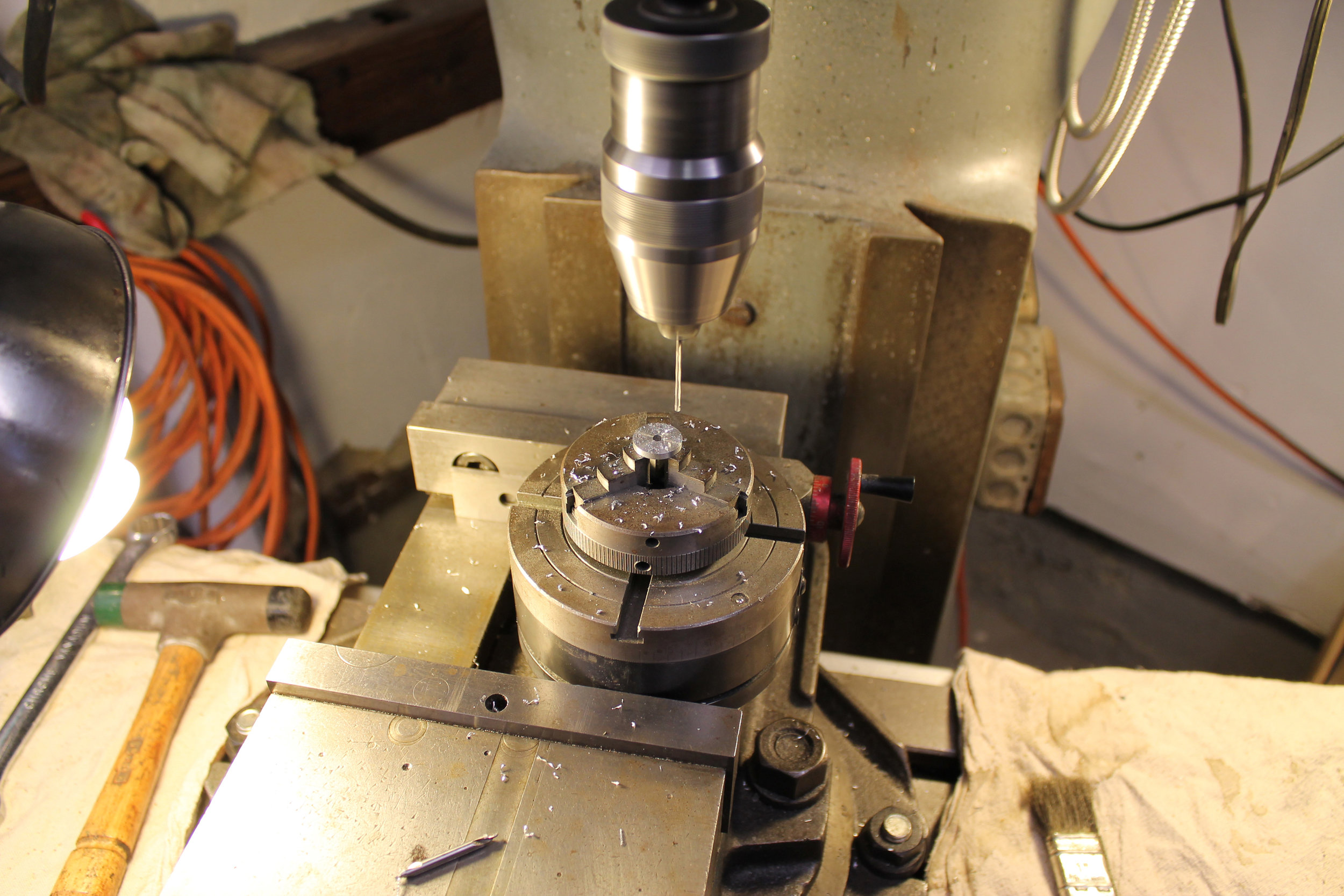
Drilling Gear Blanks with Sherline Rotary Table

In addition to the aluminum standoffs and the modified gear blanks there are other mechanical components machined from metal. These were the parts involved with moving the whole body and needed to be particularly strong. We'll discuss these when we get to the body elevation aspect of the project.
The Pre-Assembly Process

A pile of parts is pretty uninspiring. So I find it helpful and informative to assemble the components as they are produced, even though I know full well I'm going to have to take everything apart again. The fact is, the more complicated the mechanism, the more assembly and disassembly will take place. One of the guys who taught me how to do animatronics, way-back-when, told me that a project isn't done until you’ve taken it apart and put it back together at least 8 times. And 20+ years later I pretty much have to agree. It's best to keep it to a minimum, for the sake of one's own sanity, not to mention that of your employer, but a certain amount of it is unavoidable. But it's pretty damn cool to see your stuff coming together during that initial pre-assembly.


Servos were used to drive the neck of the BNPF. The servos I chose were three HiTec hs-805BB servos because they are strong, durable, inexpensive, and have nylon gears instead of metal gears. Nylon gears are not as strong as metal gears but they have better wear characteristics and will last longer if not put under too much load. The design of the 3d printed body framework is laid out so as to provide a place to mount the neck, hold the servos in place in relation to the neck, and to provide a structural pivot point for the elevation of the body. This should all become more clear as all the components come together. The elements of the body structure are designed in layers to facilitate the 3d printing process. The the aluminum standoffs connect these different layers together.


Once I am satisfied with how the various body and neck elements go together I then have to take it all apart for the electroplating process. Yay.
Electroplating Preparation
I have seen examples online of people electroplating 3d printed plastic parts but never for the purpose of making them more structural: only to make the parts prettier. I have utilized electroplating in the past with cast resin parts to make them both stronger and yes prettier. There is a huge opportunity or making lightweight 3d printed parts more suitable for use in mechanisms, and now I am going to let you in on the secret.
Primarily, the individual components of the neck and the neck strut will be electroplated. These comprise the most visually dominant elements of the BNPF and would benefit the most from being strengthened and stiffened. Some of the other visual elements will also be plated but the neck and the strut are the most mechanically crucial parts to undergo the process.
Once the components are cleaned up, the first step of the electroplating process is to give them a coat of primer. I use an automotive primer as it is of a better quality than the more generic types of primer available from your local hardware store. After the primer is applied, a fairly heavy gauge (18 to 16 gauge) of copper wire needs to be attached in order to suspend the parts in the electroplating solution. The plastic parts will want to float in the plating solution so the copper wire needs to be strong enough to keep the parts submerged during the plating process. Then, a layer of electrically conductive paint is applied to the part. Electrically conductive paint is available from plating supply companies online.
I have found it helpful to apply the conductive paint with an airbrush for anything but the smallest objects. Airbrushing helps to apply the paint evenly but it can be tricky. The conductive paint needs to be thinned down enough to pass through an airbrush but not so thin that it becomes non-conductive. My approach to this is to thin the paint just enough to be able to spray it with an airbrush and no more than that. The texture of the paint can get a little stippled, adding some roughness to the final finish of the metal plate, but I have learned to live with it. The alternatives to applying the paint with an airbrush is to use a paint brush (very labor intensive and inconsistent) or to dip the parts in conductive paint (requiring a lot of paint).


Electroplating 3d Printed Parts
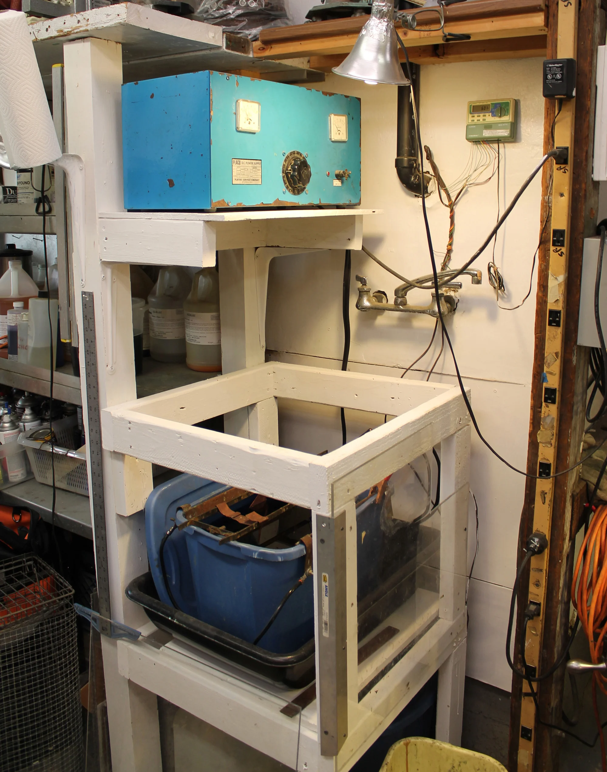
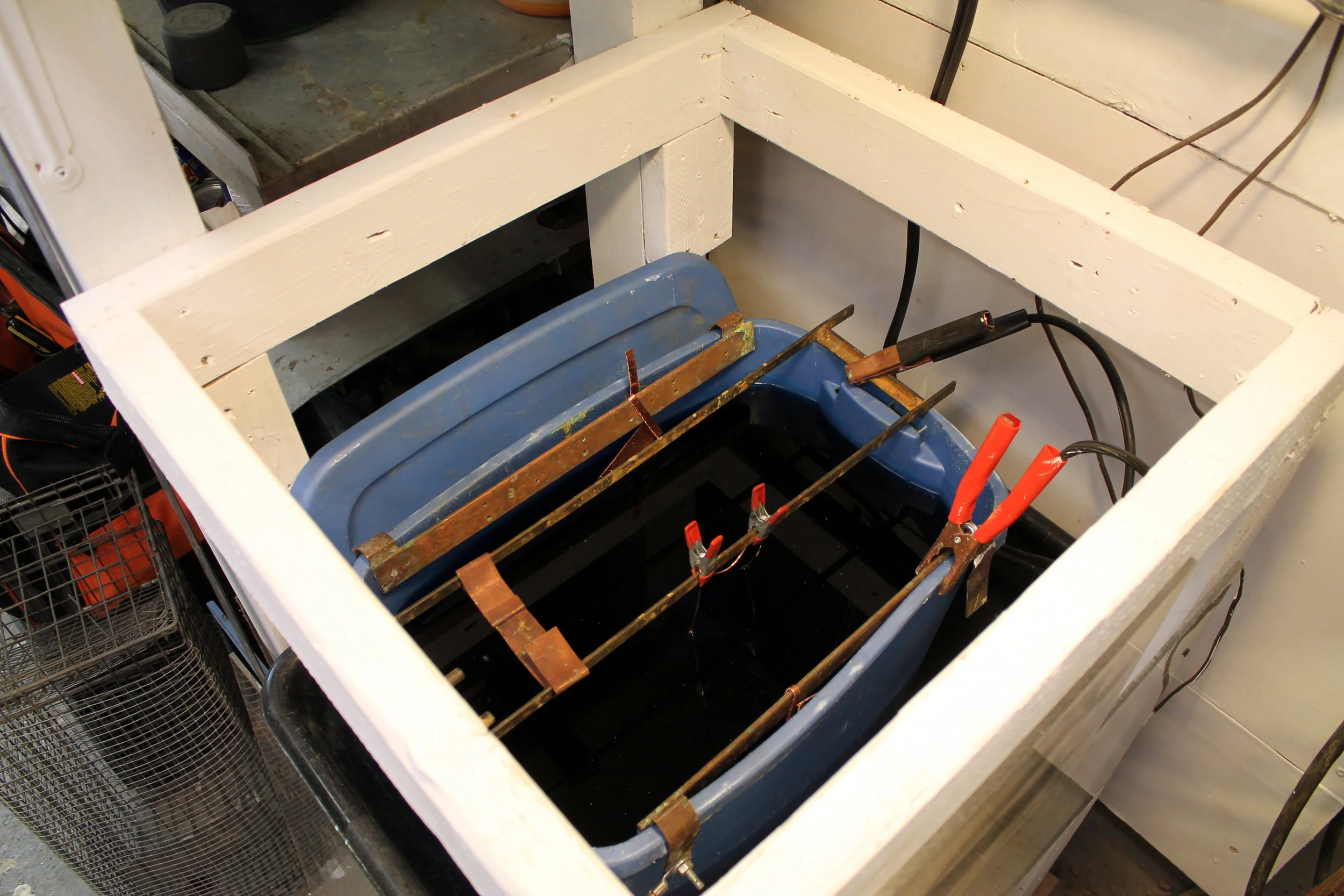
Plating Station
My electroplating system does really well with copper. Copper is the base metal for any plating operation weather it is for gold jewelry or chromed hot rod parts. I allowed the copper layer to build up on the parts for about 12 hours.This creates a layer that is plenty strong for the purposes of the BNPF.

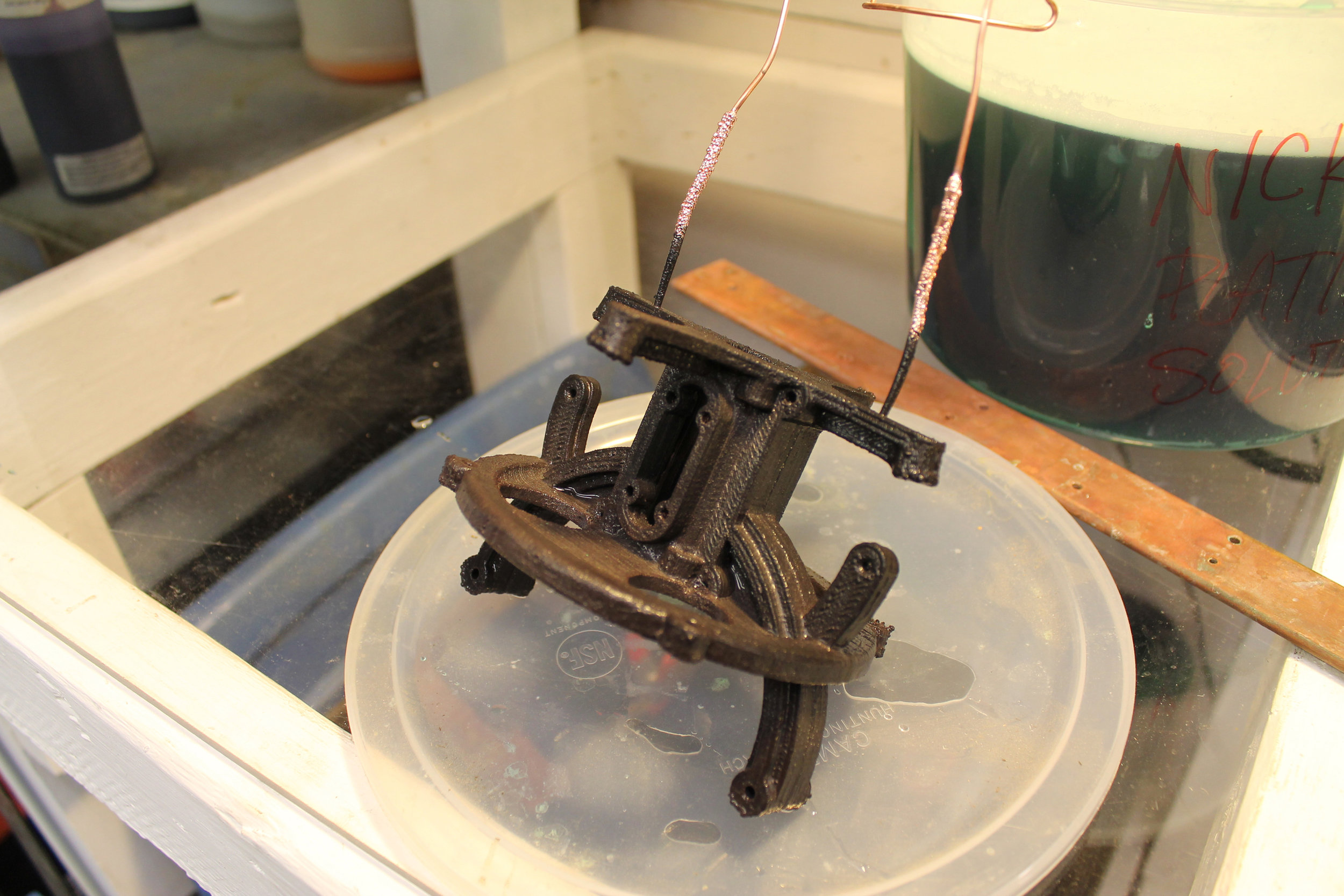
Part ready to be Electroplated
In it Goes

And Out it Comes
I also had a small amount of nickel plating solution that I thought I'd make use of, though the finish has never been quite as bright and shiny as it might have been. Don't know why, but it always comes out a little funky. We're making art here not a hot rod; I have embraced the funk. The nickel plate was allowed to go on for about 30 minutes. It came out of the plating tank looking brown and funky, but with some buffing with a soft wire wheel in a dremel tool it shined up fairly well. However, it still retained some of that funky stuff. In future projects, the funkiness increased to the point where the solution just became useless. Perhaps some chemical element was becoming depleted in the solution. Don’t know. Not worried about it. Moving on.

Nickle Plate Set Up

Fresh From the Take Looking Brown ?

Shined Up a Bit and Looking Much better

Bunches of Parts for the Plating Tank

Coated with Electroconductive paint

Arranging Parts for Plating

In They go

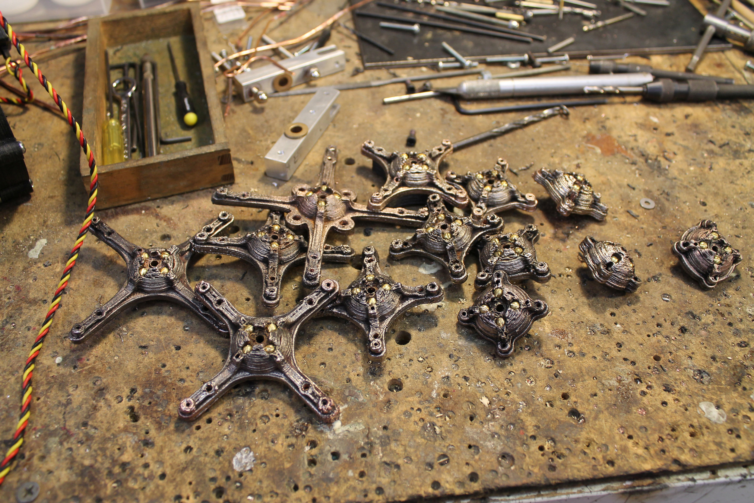
And Out they Come

Nice!

Funky Brown Nickle Plate

Put Some Shine on it

I Dig the Textures
This is Going to be the Sweetest Robot Flamingo Ever!