
The Brave new Pink Flamingo (Part 2)
/BNPF Assembly
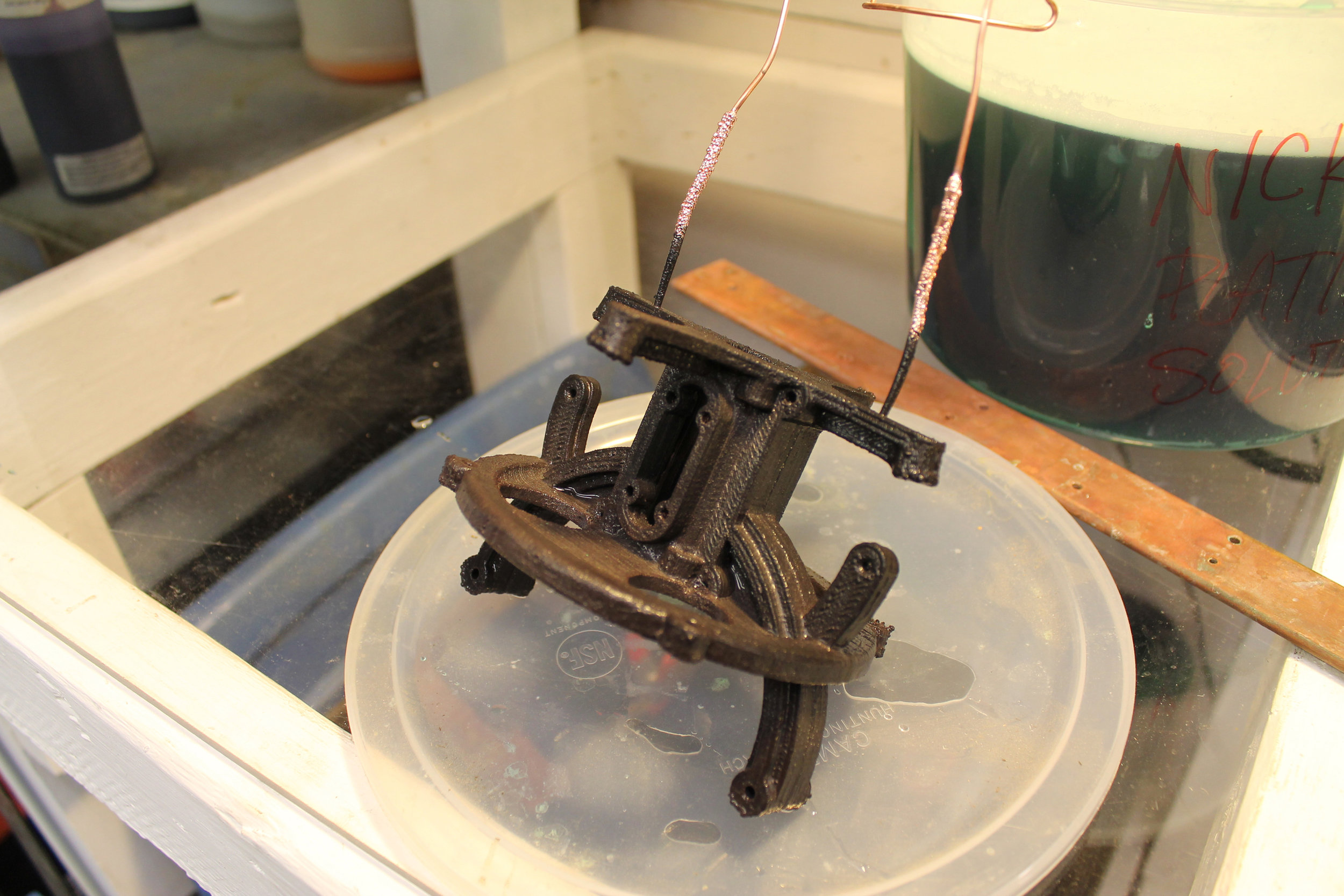
Now that the parts are electroplated, it is time to put everything together.

The Neck
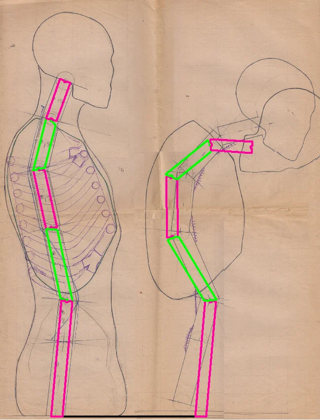
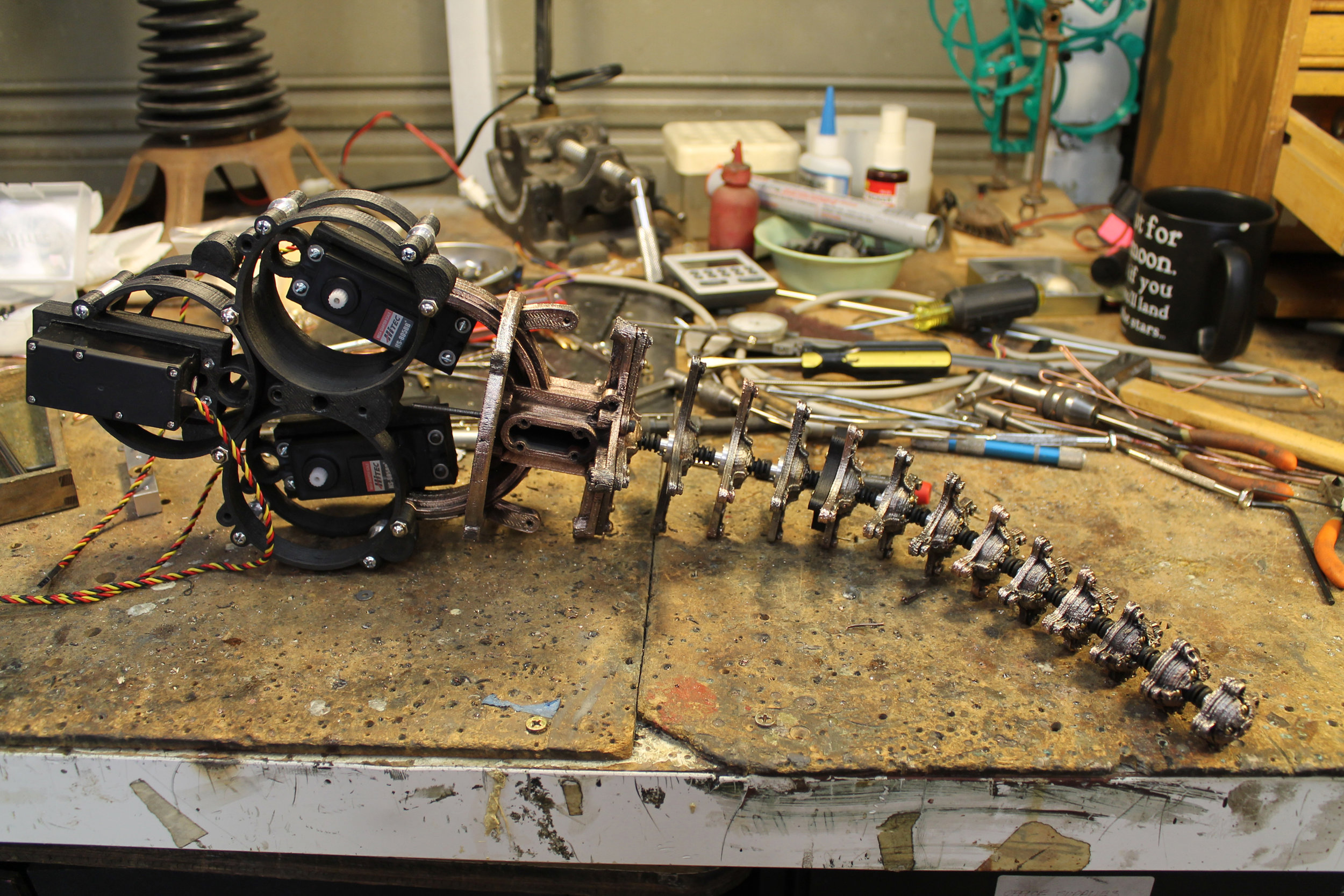
The neck is the heart of the Brave New Pink Flamingo. It is a 2-stage tentacle mechanism with a 1/8th inch diameter speedometer cable as its core.
The Body
When I started seriously considering the use of 3d printing for animatronics, my first thought was “how awesome would it be to just print up a mechanism and all I needed to do was drop the servos in?”. Well, it never really worked out that way, but I made a good attempt at that goal with this system. The body was 3d printed as three different layers, and when screwed together, accomodated three servos with pulleys and cable housing terminations, and integrated perfectly with the neck mechanism.
Ther servos I chose for this project were three Hitech 805bb servos. They are fairly strong and really cheap (~ $40 each). There are servos out there that are two thirds the size and are three times as strong, but they cost four times as much. So there you go.
The Legs
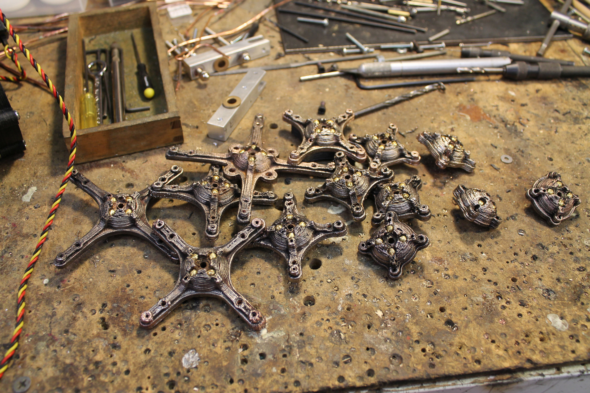
Flamingos have long legs and the Brave New Pink Flamingo is no different. This part of the project actually ended up being a tremendous lesson for me in the structural limitations of 3d printed parts.

Aw Snap! I designed and printed the components meant to serve as the legs and hips of the BNPF. After assembling these parts I didn’t like what I saw. So I gave it the “I wonder how easily I can break it” test. Oops, too easily. Back to the drawing board.

One of the great things about 3d printing is the ability it grants to try out different iterations of and idea without a lot of man hours involved. In the picture above you can see where the first leg structure failed and how I beefed it up in the second. If I had spent the time machining these parts and had this kind of failure, there would have been much wailing and gnashing of teeth. As it was, it was more a matter of “huh, look at that…”. It was a good learning experience.
Designing for the Material
When one learns to design mechanical systems made out of metal, like I did, there are certain things one takes for granted, like strength and durability. So, moving forward with this project, I had to make it a point to stop and think about what I was asking the materials to do. It’s not a difficult thing to do, but it was an interesting process, at the time.

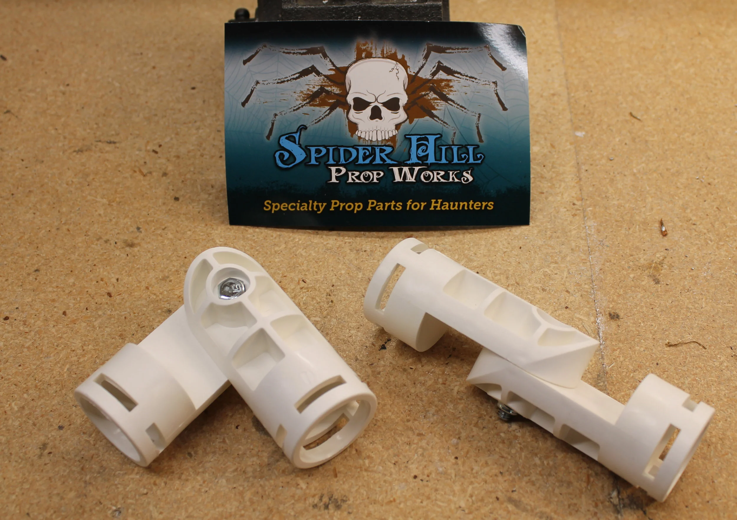
Here is an example of the shift that took place in my design approach. The project called for the whole body and neck assembly to elevate 120 degrees on a .25” diameter steel shaft suspended between the hips of the BNPF. The idea was to use a .5” bore metal shaft collar to clamp down on a printed plastic hub in order to hold that steel shaft. On the left, is the first hip hub part and the off-the-shelf shaft collar I intended to clamp down over the part. On the right is the redesigned hip hub with a much beefier seat for a much bigger shaft collar. The new shaft collar was something I had to custom make.

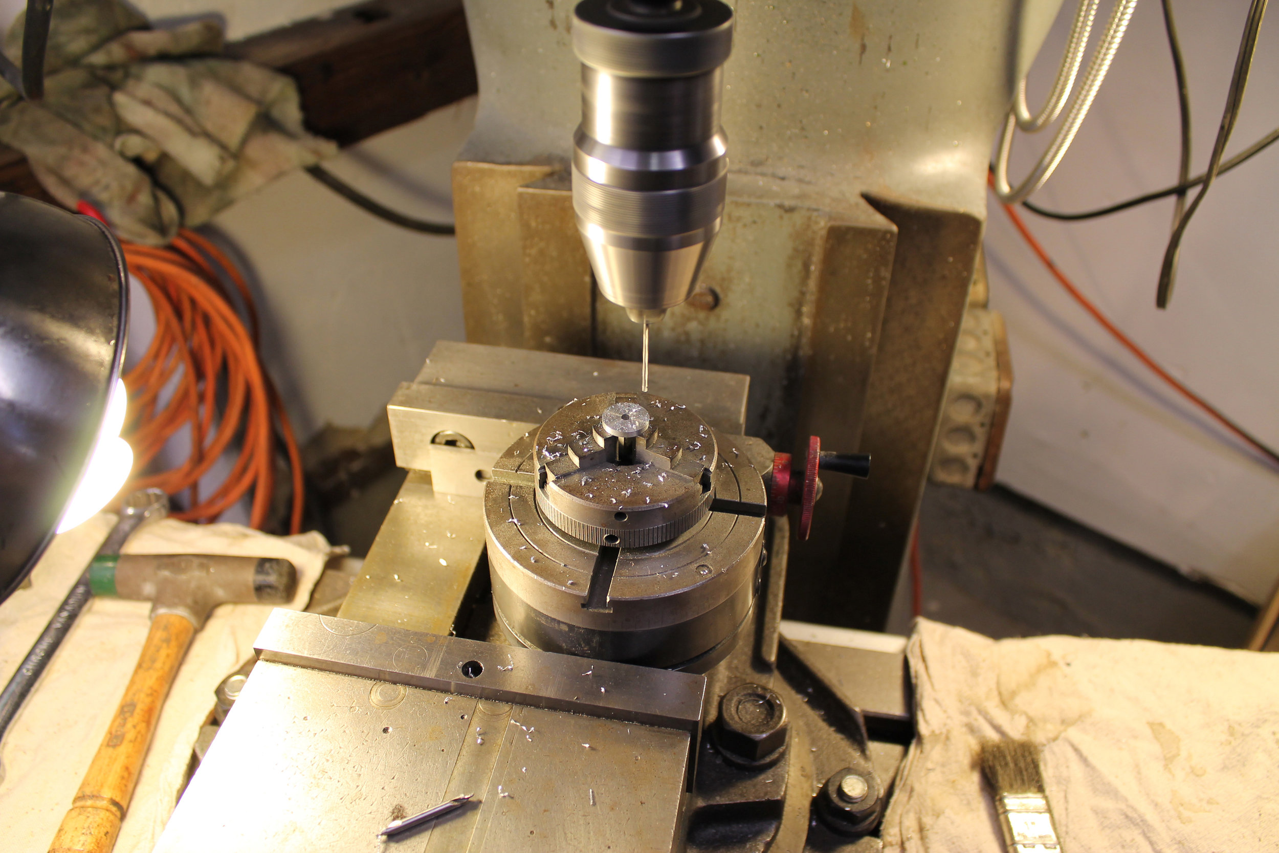
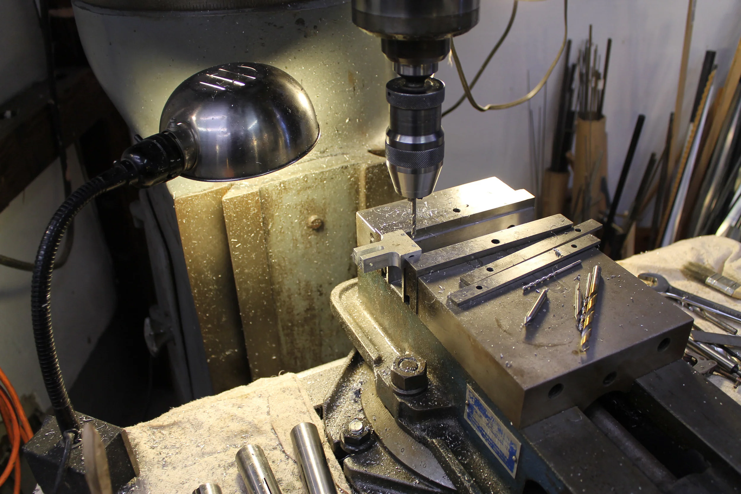
Turning custom shaft collars for the BNPF hip hub on my little vintage Craftsman lathe.
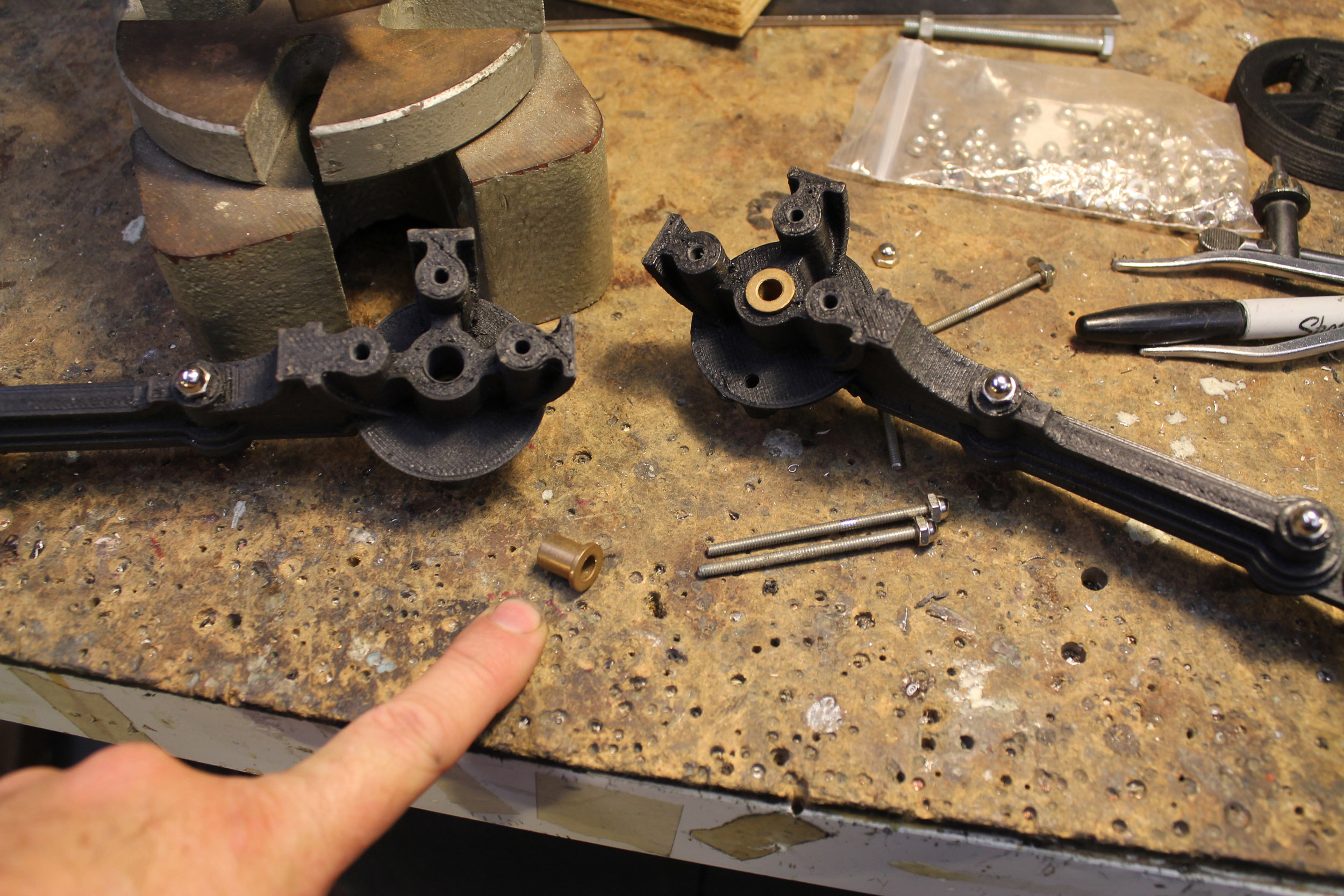
In my new found paranoia about breaking plastic components, I was very concerned about my plan to press fit bronze bushings into my 3d printed parts. I am pleased to announce that, yes, you can press fit bronze bushings into 3d printed parts.

Here is a good work around for the fact that 3d printed parts cannot be threaded: press fitted nuts in hexagonal recesses. Works great!

Here are the finished leg assemblies.
Body Elevation Mechanics
Raising and lowering the body of the BNPF was accomplished with a linear actuator from C.K. Design Technology Inc.
http://www.ckdesigntech.com/wseriesfb.html
It was during the construction of this part of the BNPF that my 3d printer started giving me problems. I had gotten most of the plastic parts I needed so I didn’t it slow me down and continued on using more traditional/old-school machining techniques. In terms of the levers, cranks, and clamps needed for this part of the project, there wasn’t much 3d printing was going to do for me, anyway.


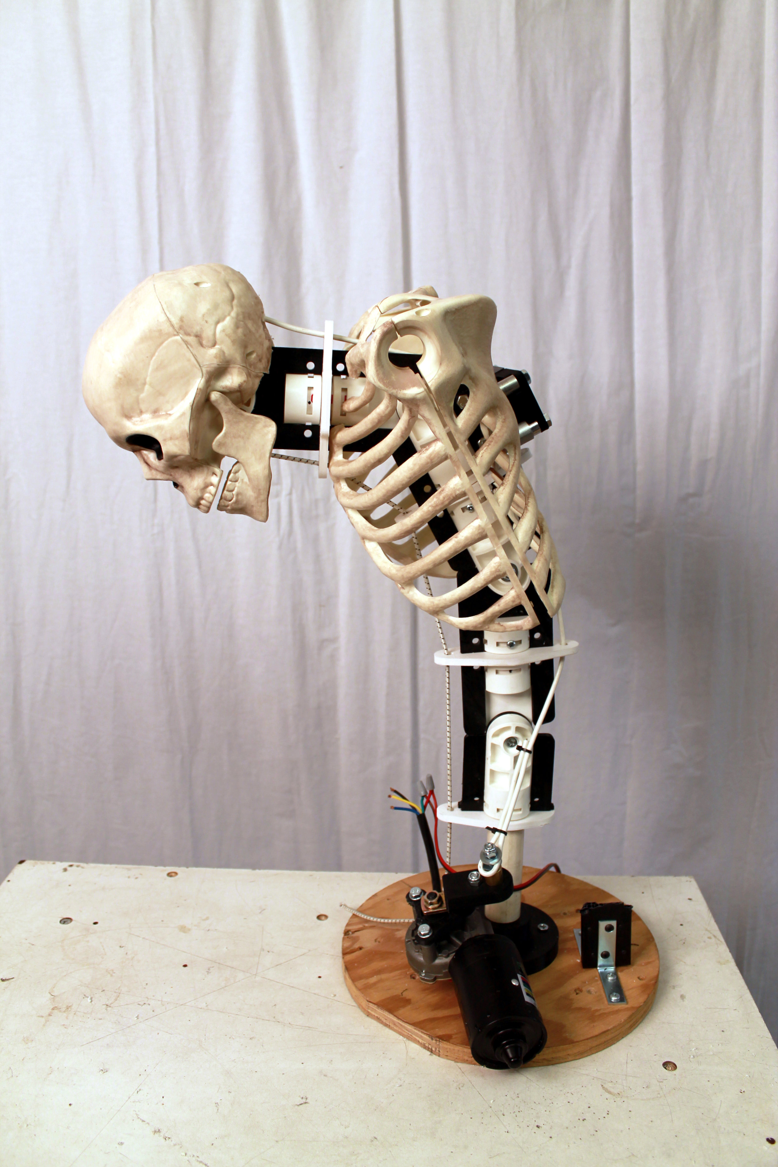
Head Mechanics
The head is a relatively simple yet critical aspect of the BNPF. It is actually made from a model of the jaws of a dragon fish. How cool is that?


The neck had to be completely installed and cabled before the head could be dealt with. There is a lot that goes into a 2-stage neck mech, especially if there is going to be a cable actuated head mounted on the end of it.

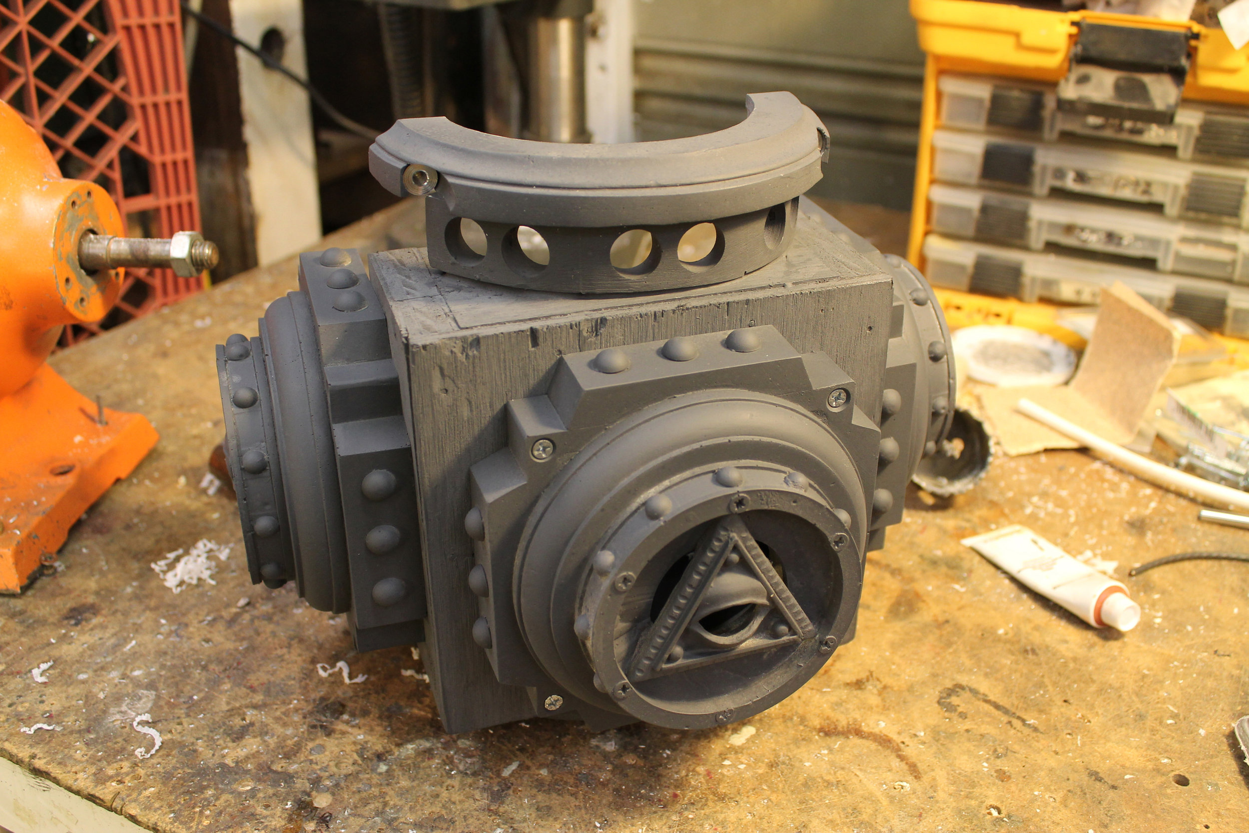
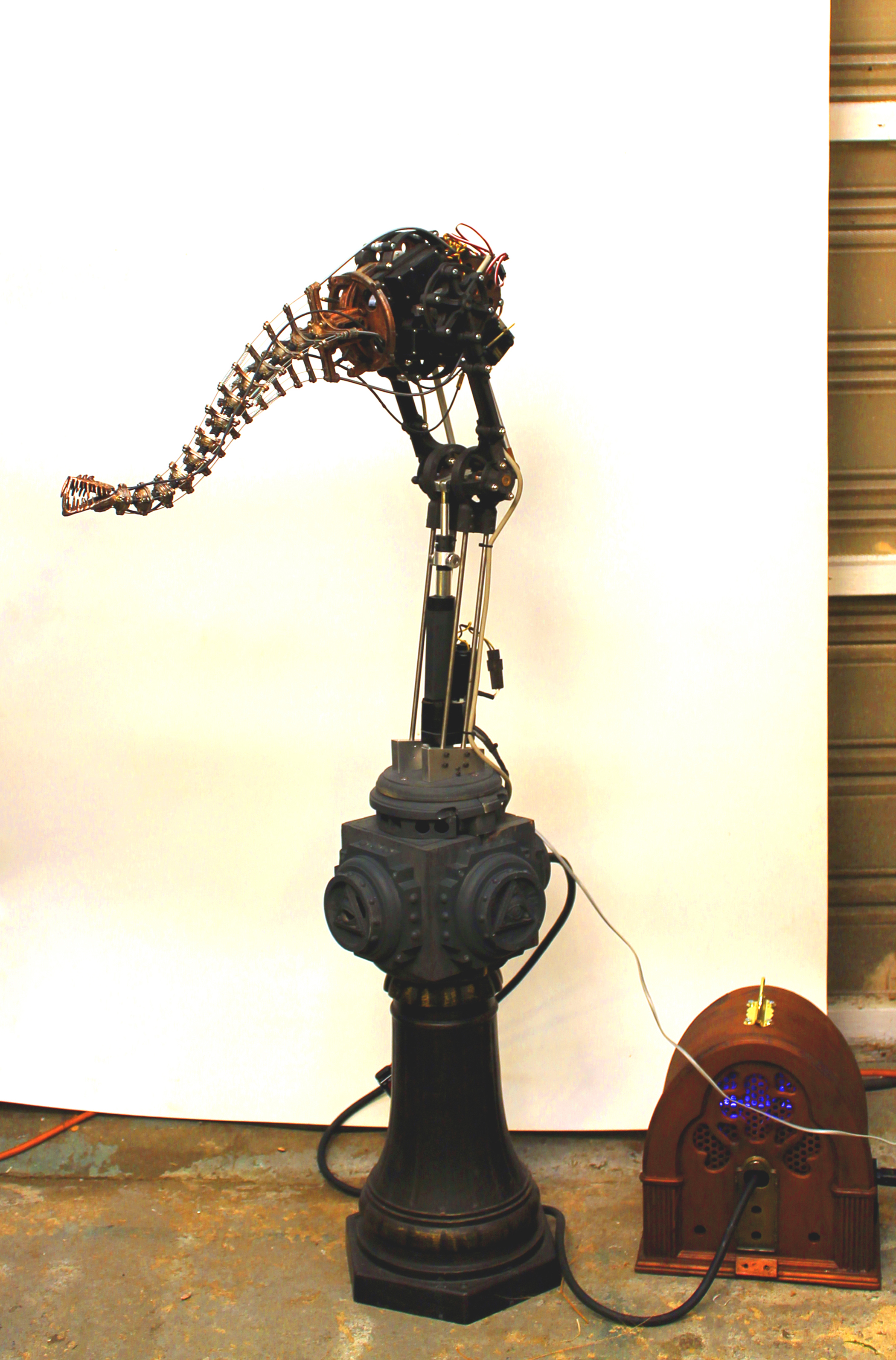
The Base
To facilitate bringing all the various elements together, the BNPF needed to be mounted on its base. I wanted this critter to stand stand fairly high in relation to the eye line of its viewers, so I chose to mount it upon a metal pedestal that was once part of a decorative lamp post. It is to be displayed in a group art show and these things need to be considered.
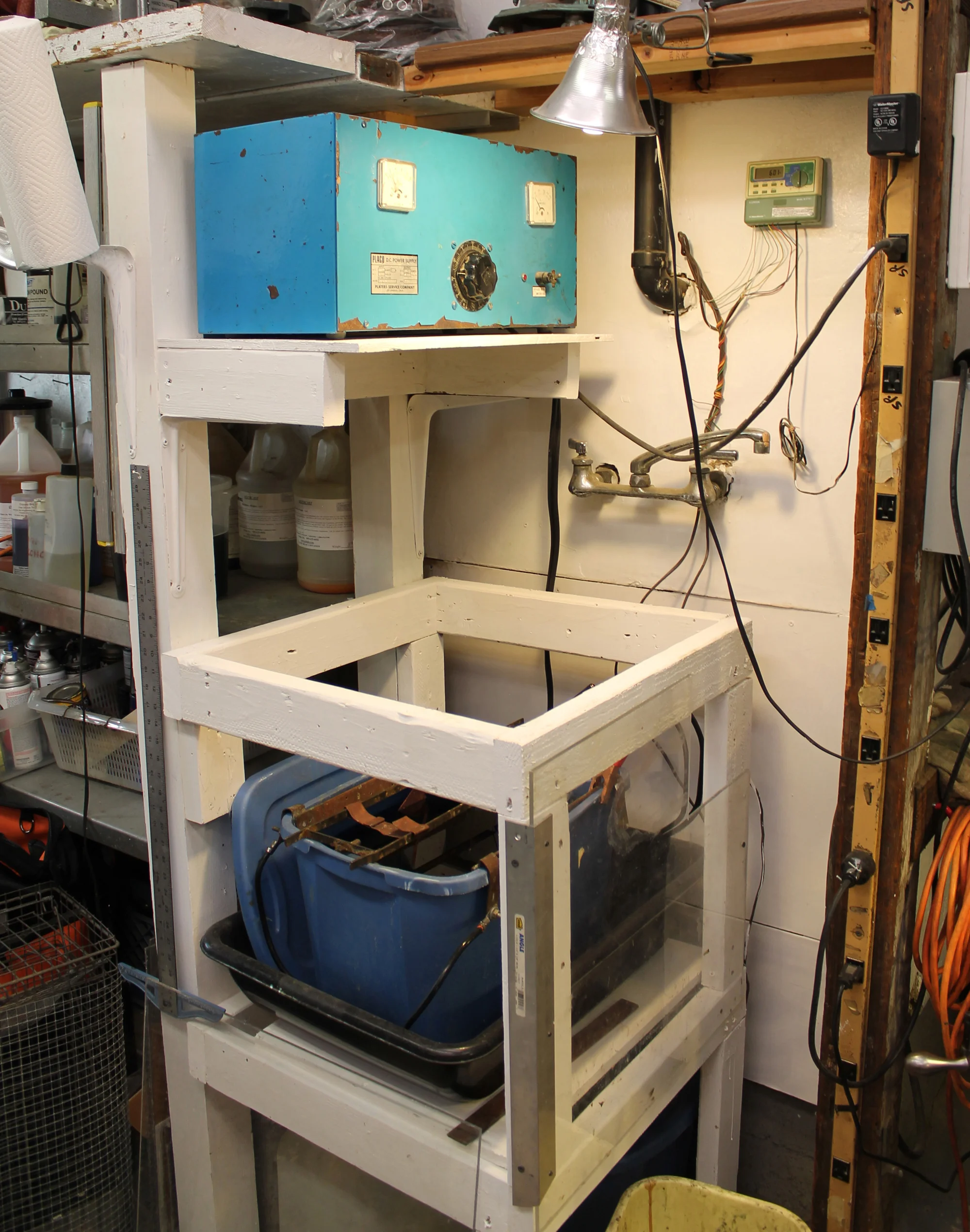
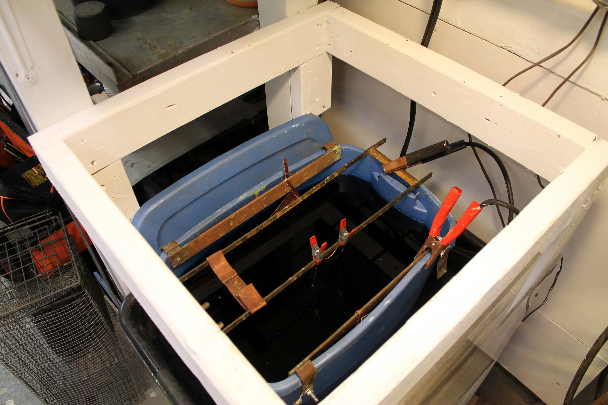
In addition to supporting the BNPF and displaying it to its best advantage, the base houses all the various electronics needed to bring this project to life (power, microcontroller, sensors, motor control) . So, it not only needs to be sturdy and look good, it’s interior needs to be accessible while the electronics are installed. The enclosure for the electronics actually required a surprising amount of work.


Power Supply and Enclosure
The electronics for the BNPF required two different power supplies and they needed some sort of decorative enclosure. I modified an old radio I picked up at a flea market to serve that purpose.


The Control Electronics
As an art piece the BNPF looked really cool. However, it was meant to be an interactive, robotic art piece, and as such, it was less than ideal. The problem was that I was using a Basic Stamp 2 as a microcontroller and its capabilities were just too limited. At the time, it was the microcontroller I knew best. The inherent limitations of the Basic Stamp 2, as well as the fact that I had run up against the deadline for the art show, meant that its performance was less than satisfactory. Ah well.
The system I had put together to control the performance of the BNPF consisted of the Basic Stamp 2, a motion sensor, and an array of three sonar range finders. The idea was that the motion sensor would alert the Basic Stamp 2 of the presence of people, the array of sonar sensors would located the location of the nearest target within range, and then the BNPF would respond with some behavior appropriate to the direction and proximity of the nearest target. I have some success in the past with this exact system with animatronic tentacle creatures, but alas, the BNPF was just a bit too complex for it to work well. It needed to be able to respond to its environment with the same level of interactivity as a pet parrot on a perch, which it really didn’t.
I was discussing this situation with Jon McPhalen, who is a big proponent of the Parallax Propellor microcontroller and he has me convinced that the Propellor is the way to go with this kind of interactive, robotic sculpture. Microcontrollers like the Basic Stamp and the Arduino are capable of doing only one thing at a time: check the sensors, move a servo position, move another servo position, check the sensors again, ect… not really what was needed. The Propellor has parallel processing, which basically means it has 8 individual processors working simultaneously. That means sensors could continuously be scanning the surroundings of the BNPF, servos could be going through complex little behavioral subroutines, and multiple emotional states could be qued up and ready to go once the sensory inputs indicated it was appropriate. Sound great right?
I know people who seemingly eat new computer languages for breakfast. I am not one of them. I have sat down a number of times with a chunk of time set aside for learning to program the Parallax Propellor in the Spin language, and every time it was a miserable experience. I found the learning curve for Spin to be brutal. The Brave New Pink Flamingo stands lobotomized in a corner of my studio to this day. So sad.

Test Circuitry with Basic Stamp 2